Buggy Build/Suspension Experiment

CSR

Active Member
Location
Mapleton
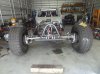
I had to try this. I've been out of the buggy game for a few years, but this idea has been rattling around in my head for a long time. If I could eliminate body roll by placing the center of gravity between the upper and lower roll axes instead of above them both, then I could have a rig that drifts like a Ferrari, jumps like a sand rail, and rides like a Cadillac, all without the use of sway bars or stiff springs. There's a lot to explain here, so I'll post pics and talk about the theory behind the build.

But to begin, here are some quick specs on the rig:
-stock LQ9 engine from a 2002 Escalade, with LS1 intake (hurts performance just a tad, but makes it clear the hood)
-TH400 with stock internals and a reverse-pattern manual valve body
-Ford NP205 t-case (these are the bomb IMHO)
-1350 drive shafts
-Ford 60 Front/5.38's/Spartan Locker/Spyntec Free-spin kit (hopefully soon)
-14 bolt rear/5.38's/mini spool
-40" Pro Comp Xtreme MT's
-Allied beadlocks
-Trail gear full hydro
-ADS 2.5" shocks front, 2.0" rear
-Summit radiator
-Low Range Off Road flex joints
-Smitty Bilt XRC 9500 winch
-Trail Gear limit straps

DSC03951.jpg
 
Last edited:

CSR

Active Member
Location
Mapleton
Here's a look at the front. 2005 Super Duty front axle. I chose this axle because of how far the pumpkin is offset to the driver's side. I needed this in order to have the drive shaft over far enough to clear the engine on up travel...all 13 inches of up travel:eek:. The engine is offset 3 inches to the passenger side of the rig to make room for the left-to-right motion of the pinion yoke through the range of suspension travel. Also this housing is massive! 3 3/4" OD x .500 wall tubing. Yes, it's heavy, which is not good for speed, but hopefully having the engine mounted above it will counteract the force of the axle being thrown upward in the whoopty-do's. The knuckles and inner C's are also huge, which I like. More to come on knuckle modification.
 

Attachments

  • DSC03946.jpg
    DSC03946.jpg
    1.3 MB · Views: 92

CSR

Active Member
Location
Mapleton
DSC03950.jpgDSC03952.jpgDSC03957.jpg
So here's what I was talking about regarding center-of-gravity-relative-to-roll-axis positioning. You can see that the upper link mounting points are really high front and rear. It's a very unorthodox look, but it places the drive train and most of the chassis (i.e. the center of gravity) in between the upper and lower roll axes, which means no body roll on hard cornering. You can also see that the front axle is waaaay out front (120" wheelbase). This was done to allow the axle to travel 13" upward from ride height without hitting the engine. The rear axle also has clearance to travel 13" upward.

With this much upward travel available, I can use really soft upper coils on my dual rate setup so that I have a super soft ride through about 6" worth of up travel. Then the 300 lb lower coils take over on the really hard hits, and stop the rig from bottoming out with the remaining 7" of up travel at the higher spring rate.

I built the entire rig on the ground at full stuff to make sure everything clears on up travel. It looks funny when I take the spring coils off and lower the thing to full stuff where it's just riding on fully compressed shocks. The engine skid clears the ground by about 1/2 inch, and it looks like a Mad Max-inspired T-bucket.
 

CSR

Active Member
Location
Mapleton
This whole thing is an experiment, and I hope my logic is sound. We'll see when I get it out. It could be great, or it could blow up in my face after 1000 hours of labor. Either way, I will have at least scratched the itch to find out.
 

mbryson

.......a few dollars more
Supporting Member
I am curious how your "truss" holds up and what forces are placed on that? It might not be any kind of issue at all with the link mounting points countering any leverage action against the "upper mount" on the axle? Very interesting and clever idea. The more I think about the stresses,the more I think you've probably accounted for them with the multiple points tied to the axle
 

CSR

Active Member
Location
Mapleton
Engine Pics. Kind of a shoe-horn fit, but it's all there. I re-worked my own harness using the info on LT1swap.com. The website is great for information, but man is it a lot of work. I wanted my harness to be fully custom on this rig without having weird lengths of stuff everywhere to tuck away and hide. So after about 60 hours of soldering and heat shrinking every stinking wire in the harness, I have what I want. I'm telling you, folks, $500 to get your harness mod done at Jim's Performance or elsewhere is a DEAL!

DSC03961.jpgDSC03962.jpg
 

CSR

Active Member
Location
Mapleton
I am curious how your "truss" holds up and what forces are placed on that? It might not be any kind of issue at all with the link mounting points countering any leverage action against the "upper mount" on the axle? Very interesting and clever idea. The more I think about the stresses,the more I think you've probably accounted for them with the multiple points tied to the axle

Yes, I thought a lot about that. The links themselves will be relatively unstressed because of the leverage advantage they have with such a tall tower. But the point at the base of the tower where it welds to the housing will be stressed pretty good. I welded DOM supports on the front tower, and on the rear, I incorporated bolt-on attachment points to both the 3/8" thick diff cover flange, as well as the front side of the truss that bolts to the pinion support. It's not going anywhere.
 

CSR

Active Member
Location
Mapleton
More on the knuckle...

As you can see in the pics, I'm using 2 inch wheel spacers in the front for two reasons
1. I like width (I know, I know,...stresses)
2. I needed to adapt from the metric Ford pattern to the standard 8 on 6.5 pattern

This increases leverage a lot against the ball joints and steering. The steering stresses I'll have to live with (at least I'm not running a spool :)). But the ball joint stresses worried me. Upon inspection of the factory ball joints, I noticed that the lower joints are big, kinda sorta in the ballpark of kingpins. I also know from some experience that lower ball joints don't loosen as often as upper ones. I wanted that strength at the top of the knuckle, so I built a fixture and used my brother's mill to machine out the upper ball joint bore on the knuckle to accept a lower ball joint. Then, I used his 4-jaw chuck lathe to machine the camber/caster insert to work with the lower ball joint in the upper bore. You can see there is a lower ball joint in the upper part of the knuckle in the picture. I think this will help a ton with reliability given the leverage stresses of my wheel spacer set-up. To top it off, I also used my brother's mill to machine a key into the top of the knuckles. Then I cut my own steering arms from a 1" thick steel bar he had laying around and machined a key way into them. So with a key way, 4 grade 8 1/2" bolts, and a double-shear set-up, it should be good.
DSC03949.jpg
 
Last edited:

CSR

Active Member
Location
Mapleton
DSC03953.jpg
Here's the front suspensions set-up. I used 2x2x.25" square tubing for the lower arms and then added additional 2x2x.25 pieces of square tubing for bracing. I bent the arms downward enough to position the lower shock eye below the center line of the flex joint eyes so that the arm would self-center, kind of like a hammock. This cost me some ground clearance, but I'm fine with that.

The shocks mount in the middle of the arms, which doubles the up travel of the axle relative to the up travel of the shock. The backward angle of the shock increases this ratio a little more. I'm using 400 lb/in springs up front which seems just about right so far. Mounting the shock in the middle of the arm allows me to have serious up travel without having a mile-high shock hoop sticking out the top of the hood.

Also, there's a velocity factor involved here that should smooth out the ride a lot. When the front axle hits a bump, it travels upward at a certain distance over time, aka velocity. The shock also travels upward, but at half the velocity because it is mounted farther back. This reduces the loading rate of energy into the chassis by half, which should make things a lot smoother.

That's the theory, anyway. Thoughts on this, anyone?
 

CSR

Active Member
Location
Mapleton
DSC03955.jpg

I mounted the switches and gauges up top. I'm a fan of leg room and footwell space, so I didn't want a dash to take up space. the wiring is also easier to get to like this.
 

CSR

Active Member
Location
Mapleton
DSC03958.jpgDSC03959.jpgDSC03960.jpg

Rear end pics. Rig is only 5'7" at the top of the roof. 17" of ground clearance, not a lot, but I'll always take stability over ground clearance. Long, low, and hopefully fast. Can't wait to get her finished up and tried out.
 

I Lean

Mbryson's hairdresser
Vendor
Location
Utah
Also, there's a velocity factor involved here that should smooth out the ride a lot. When the front axle hits a bump, it travels upward at a certain distance over time, aka velocity. The shock also travels upward, but at half the velocity because it is mounted farther back. This reduces the loading rate of energy into the chassis by half, which should make things a lot smoother.

The shock travels half the distance/velocity, but with twice the spring rate and damping. (to make an equivalent difference at the wheel)
 

CSR

Active Member
Location
Mapleton
The shock travels half the distance/velocity, but with twice the spring rate and damping. (to make an equivalent difference at the wheel)

Yeah, I may be figuring wrong on that, but at least the set-up still keeps everything under the hood.
 

Herzog

somewhat damaged
Admin
Location
Wyoming
Now this is cool. I'm really liking your train of thought here, especially how different but logical it is. Subscribed!
 

CSR

Active Member
Location
Mapleton
Thanks. I have thought for a long time that a vehicle should be "down inside" the suspension, rather than teetering on top of it. It's definitely different, but it might just work really well. I'm hoping I can drift on dry pavement without body roll, rock crawl reasonably well, jump it, and hit the whoops at Little Sahara.
 

bryson

RME Resident Ninja
Supporting Member
Location
West Jordan
Very interesting, and because of that, I like it. However, your limiting straps make it look like there is almost no down travel... Am I missing something?
 
Top