
Disclaimer: I have no idea if this is the right/proper/safe way to do this. This is the way I did it. Your results may vary. You tamper with your vehicle's electrical system at your own risk.
Utah safety inspection requires a full compliment of fully-functional lights. If you have modified your grill or bumper you may need to add lights back in to satisfy the requirements. Round grommet-mounted lights are nice to use because they can be installed easily, cheaply, and cleanly. The LED versions of these lights are durable, low profile, and don't create heat, so they are a natural choice. The drawback of these LEDs is that dual-element versions are not available (at least not that I could find), so using a single light as a parking light, turn signal, and hazard light is difficult. It can be accomplished by wiring a resistor into the parking light lead to reduce the brightness of the light when only the parking lights are on, and isolating the parking and turning leads with diodes to protect the each circuit from the voltage of the other lead. Here's how I did mine:
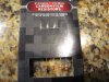
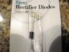
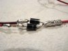
These are the resistors and diodes I used:


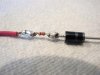
The parking lights need to be dimmer than the turn signals and hazard lights, so the power lead for the parking lights will have the resistor wired into it to reduce the current going to the light. After the resistor I added a diode to keep the power from the turn signals and hazard lights from feeding back up through the parking light lead. Make sure you orient the diode in the right direction or the parking lights will not work, and the turn signal power will run back through the parking light wire possibly damaging the electrical system!

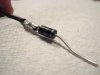
The turn signal and hazard lights need to be the full brightness of the light, so no resistor is required on their power wire. I did wire a diode into this lead to prevent the power from the parking lights from feeding back through the turn signal lead.

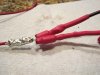
I then connected the other ends of the the diodes to the light positive lead.

The two input wires before the diodes need to be isolated from each other, so I wrapped each one with heat-shrink tubing.

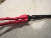
Then I wrapped the final soldered connection with heat-shrink tubing to protect it from the elements and to add strength.

Then I just wired the leads before the diodes into the vehicle wiring harness, and the single wire after the diodes to the positive side of the light. Here is the result:
[YOUTUBE]vJIdKcyefvU[/YOUTUBE]
Utah safety inspection requires a full compliment of fully-functional lights. If you have modified your grill or bumper you may need to add lights back in to satisfy the requirements. Round grommet-mounted lights are nice to use because they can be installed easily, cheaply, and cleanly. The LED versions of these lights are durable, low profile, and don't create heat, so they are a natural choice. The drawback of these LEDs is that dual-element versions are not available (at least not that I could find), so using a single light as a parking light, turn signal, and hazard light is difficult. It can be accomplished by wiring a resistor into the parking light lead to reduce the brightness of the light when only the parking lights are on, and isolating the parking and turning leads with diodes to protect the each circuit from the voltage of the other lead. Here's how I did mine:
These are the resistors and diodes I used:
The parking lights need to be dimmer than the turn signals and hazard lights, so the power lead for the parking lights will have the resistor wired into it to reduce the current going to the light. After the resistor I added a diode to keep the power from the turn signals and hazard lights from feeding back up through the parking light lead. Make sure you orient the diode in the right direction or the parking lights will not work, and the turn signal power will run back through the parking light wire possibly damaging the electrical system!
The turn signal and hazard lights need to be the full brightness of the light, so no resistor is required on their power wire. I did wire a diode into this lead to prevent the power from the parking lights from feeding back through the turn signal lead.
I then connected the other ends of the the diodes to the light positive lead.
The two input wires before the diodes need to be isolated from each other, so I wrapped each one with heat-shrink tubing.
Then I wrapped the final soldered connection with heat-shrink tubing to protect it from the elements and to add strength.
Then I just wired the leads before the diodes into the vehicle wiring harness, and the single wire after the diodes to the positive side of the light. Here is the result:
[YOUTUBE]vJIdKcyefvU[/YOUTUBE]
Attachments
Last edited:
")
