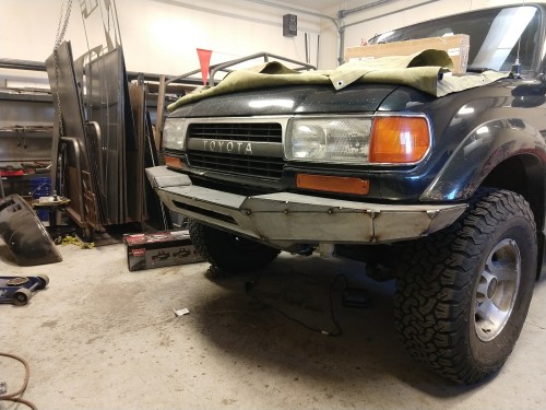
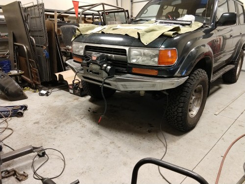
I finished up the front bumper build on my 80 today, and wanted to share my process for anyone interested, or maybe to help someone tackle their own build. (don’t be scared, it’s just metal!)
I had an idea in my head of how I wanted it to turn out, so I started with a few measurements of the frame, distance to the grill and valence, etc. Drew up the middle section where the winch will mount, along with a frame cutting template, and cut them out of 16ga sheet.
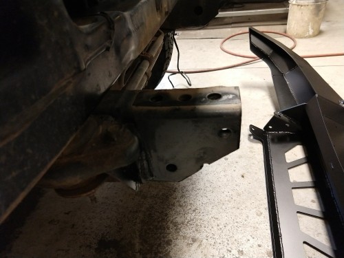
Frame cut looks like this…it eliminates one of the 3 threaded holes on the bottom of the frame. I did that to tuck the bottom edge of the bumper in tighter, since the winch is mounting up higher. There are still two holes on both top and bottom of the frame that will be used.
Initial winch mount mockup:
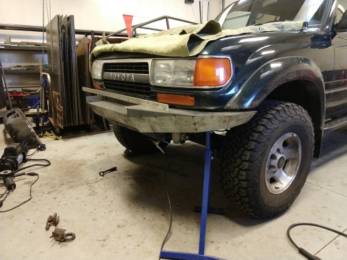
Next I used poster board to figure out a close approximation of the curve needed to match the curve of the Cruiser, then cut it out of 18ga sheet. I tacked it on, and placed the winch on the middle to make sure there was enough room between the bent inner side of the outer wing. There was plenty, but I realized there wasn’t enough space to actually bolt the winch in place unless I cut into the grill and valence to recess the winch into that space.
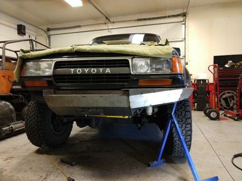
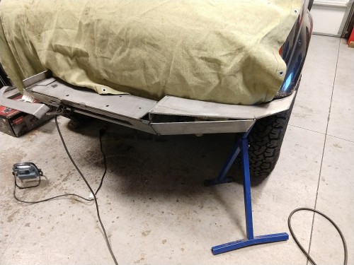
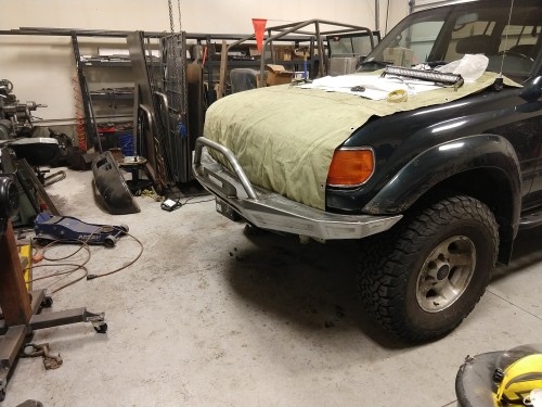
I settled on extending the bumper forward an additional inch. I didn’t redo the center section, since I already verified the dimensions I needed there. I revised the outer wing piece and tacked in on, then once again used poster board to get the dimensions and angles for the lower pieces. Convert those to 18ga and tack them in, then repeat…eventually end up here:
You can see in this one how the center is no longer lined up with the 1” extended outer wing.
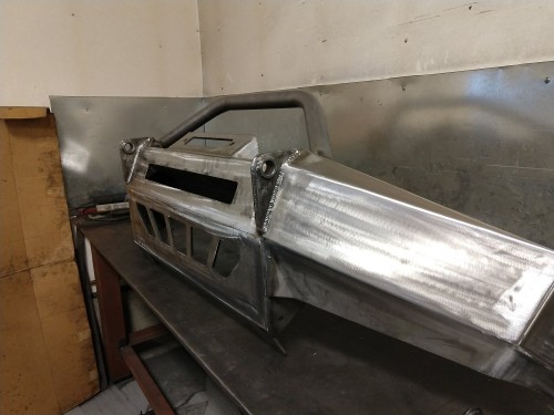
A few minor changes along the way, and I was ready to commit to cutting all the parts out of “real” steel. The center parts (winch plate, vertical side plates, and front fascia) are all made from 1/4” steel, all the rest is 3/16”. I cut slots in the 1/4” parts so I could bend it over the edge of my table…they got welded up along with the rest of the joints.
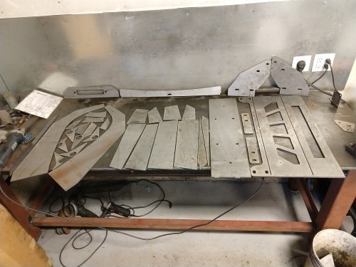
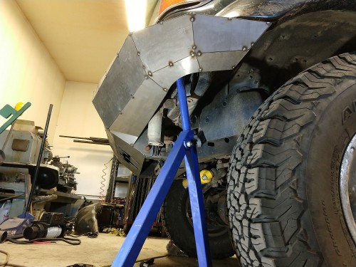
This version assembles the same way the mockup did…bolt on the vertical sides, bend the front, slide the winch plate into the slots, and weld. Bend the top plate where it meets the winch plate, and tack in. Then move on to the lower faces.
All tacked, and a few heavier welds to make sure it’s solid as I remove it for welding:
I had an idea in my head of how I wanted it to turn out, so I started with a few measurements of the frame, distance to the grill and valence, etc. Drew up the middle section where the winch will mount, along with a frame cutting template, and cut them out of 16ga sheet.
Frame cut looks like this…it eliminates one of the 3 threaded holes on the bottom of the frame. I did that to tuck the bottom edge of the bumper in tighter, since the winch is mounting up higher. There are still two holes on both top and bottom of the frame that will be used.
Initial winch mount mockup:
Next I used poster board to figure out a close approximation of the curve needed to match the curve of the Cruiser, then cut it out of 18ga sheet. I tacked it on, and placed the winch on the middle to make sure there was enough room between the bent inner side of the outer wing. There was plenty, but I realized there wasn’t enough space to actually bolt the winch in place unless I cut into the grill and valence to recess the winch into that space.
I settled on extending the bumper forward an additional inch. I didn’t redo the center section, since I already verified the dimensions I needed there. I revised the outer wing piece and tacked in on, then once again used poster board to get the dimensions and angles for the lower pieces. Convert those to 18ga and tack them in, then repeat…eventually end up here:
You can see in this one how the center is no longer lined up with the 1” extended outer wing.
A few minor changes along the way, and I was ready to commit to cutting all the parts out of “real” steel. The center parts (winch plate, vertical side plates, and front fascia) are all made from 1/4” steel, all the rest is 3/16”. I cut slots in the 1/4” parts so I could bend it over the edge of my table…they got welded up along with the rest of the joints.
This version assembles the same way the mockup did…bolt on the vertical sides, bend the front, slide the winch plate into the slots, and weld. Bend the top plate where it meets the winch plate, and tack in. Then move on to the lower faces.
All tacked, and a few heavier welds to make sure it’s solid as I remove it for welding:
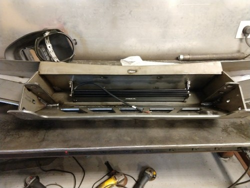
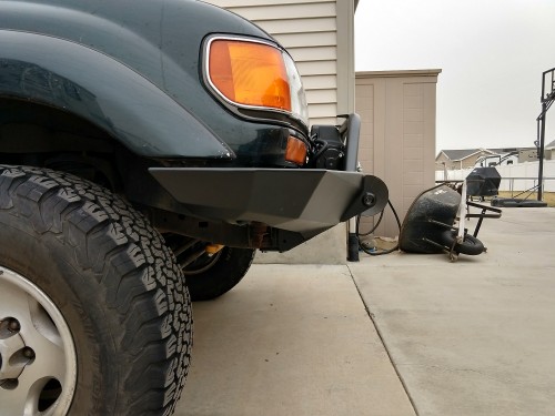
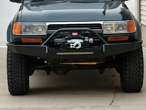
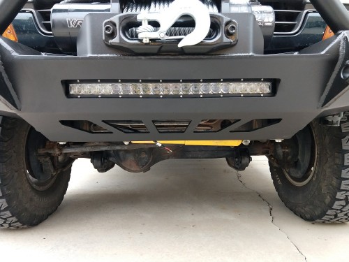
") If you look close enough, you can see the “hood” I welded in to fill the space around the top and sides of the light bar, since the face of the bumper is not vertical.
If you look close enough, you can see the “hood” I welded in to fill the space around the top and sides of the light bar, since the face of the bumper is not vertical.