
You are using an out of date browser. It may not display this or other websites correctly.
You should upgrade or use an alternative browser.
You should upgrade or use an alternative browser.
Gawynz Buggy Thread
- Thread starter Gawynz
- Start date
- Location
- The Land Northward (Bountiful), Utah
Looking good!
xjtony
Well-Known Member
- Location
- Grantsville, Ut
Coming along nicely!
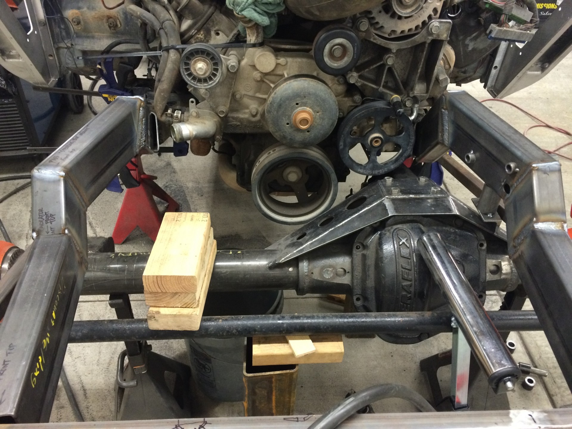
So I was trying to map out how I was going to move the frame in to avoid the pinion at passenger side high and then I thought, "hey, I have a nice prebent piece of tubing..."

Cut the old front wishbone in half and trimmed down one of the bends until it fit nicely. I'll do some final cleaning up of the end and cap off that tube later. Also, I don't like that I had to butt joint the chassis together and due to it being bent I couldn't sleeve it with anything so I plan to put gussets on each end of the added piece to tie it all together better. Bottom left picture shows ride height, the bottom center and right picture show clearance at driver full droop and passenger full stuff. Muy better. To save a few bucks, i'll be going with a home brewed rotten broom handle two piece driveshaft...
So earlier I thought I'd try to just use the old lower leading arms, even though I wasn't totally happy with them because I really want to get this thing out and go wheeling. But after staring at it and thinking about it I couldn't leave it alone. The old leading arms was 40" long from the chassis side heim to the center of the axle tube; the coilover was mounted 17.5" from the chassis side heim so that's a ratio of like 56/44 giving the axle side a huge amount of leverage and is asking the coilover to do a lot of work. On top of that, at this ratio the wheel had the capability to travel 23" and that's not even accounting for the steep angle the coilovers were mounted at so it'd be even more! But I definitely couldn't use all that travel without hitting other things so it was strapped. So I decided to make new lowers and remount the coilovers.
Problem #1, I had to remount the steering reservoir/filter to get it out of the way for the coilover mount. It's so tight near the front of the engine that there's no great spot to mount the reservoir. So I remounted some of my electrical to make room to remount my reservoir in the cab near the pedals. The outlet of the reservoir is above the pump input which is good but the two are so far separated that I'm worried that on climbs this may screw up my steering if the pump can't pull fluid. Currently it's just tacked in place but right now this looks like my best option.

Problem #2, the alternator is in the way. Given that my link separation is so big on the axle side, the axle really swings left to right during articulation (just like on the rear). With where I want to mount the coilovers, at driver side high articulation the coilover would hit the alternator.

The way that the alternator was mounted it stuck out quite a lot, I was able to make a couple brackets to remount it and reduce the belt size by 3" in circumference pulling it in quite a bit (before and after below, hopefully it's enough). Also ordered some fittings/bends to reroute the radiator hose.

So finally I started on the leading arms. My plan is to keep the same leading arm length and target wheel travel of around 16" with the 10" coilovers; to do that I'll mount the coilovers 27" forward of the chassis side heim which is about 2/3 up the lever arm. This should give me ~15" of travel, but accounting for the coilover mounting angle should end up somewhere more around 16". I'm targeting 8" up travel 8" down. Moving the coilover forward should be easier on the coilover and also allow me to use the full stroke.
The important thing is to make sure that the coilover eylet is below the rotational axis of the two heims. I put together a simple model to get my dimensions and kind of map out in my mind what I wanted to do. I considered using 2" - 1/4" wall DOM but seemed a lot more difficult to build and I don't think it'd be that much stronger if any for this application. My old lowers were 2" - 1/4" wall square tubing and I've banged on them quite a bit without issue so I went that route again.


Last night I started cutting/tacking everything together. You can see it's a pretty substantial difference compared to the old leading arm.

Plan to get the other side leading arm tacked together, figure out coilover chassis side mounting, articulate everything checking clearances, then final weld it all. Have to remake a few steering hoses and reroute my radiator hose. Order a driveshaft. Remount the winch (a little worried about this). And.... probably 10 other things in between but I'm starting to see the finish line.
Cut the old front wishbone in half and trimmed down one of the bends until it fit nicely. I'll do some final cleaning up of the end and cap off that tube later. Also, I don't like that I had to butt joint the chassis together and due to it being bent I couldn't sleeve it with anything so I plan to put gussets on each end of the added piece to tie it all together better. Bottom left picture shows ride height, the bottom center and right picture show clearance at driver full droop and passenger full stuff. Muy better. To save a few bucks, i'll be going with a home brewed rotten broom handle two piece driveshaft...
So earlier I thought I'd try to just use the old lower leading arms, even though I wasn't totally happy with them because I really want to get this thing out and go wheeling. But after staring at it and thinking about it I couldn't leave it alone. The old leading arms was 40" long from the chassis side heim to the center of the axle tube; the coilover was mounted 17.5" from the chassis side heim so that's a ratio of like 56/44 giving the axle side a huge amount of leverage and is asking the coilover to do a lot of work. On top of that, at this ratio the wheel had the capability to travel 23" and that's not even accounting for the steep angle the coilovers were mounted at so it'd be even more! But I definitely couldn't use all that travel without hitting other things so it was strapped. So I decided to make new lowers and remount the coilovers.
Problem #1, I had to remount the steering reservoir/filter to get it out of the way for the coilover mount. It's so tight near the front of the engine that there's no great spot to mount the reservoir. So I remounted some of my electrical to make room to remount my reservoir in the cab near the pedals. The outlet of the reservoir is above the pump input which is good but the two are so far separated that I'm worried that on climbs this may screw up my steering if the pump can't pull fluid. Currently it's just tacked in place but right now this looks like my best option.
Problem #2, the alternator is in the way. Given that my link separation is so big on the axle side, the axle really swings left to right during articulation (just like on the rear). With where I want to mount the coilovers, at driver side high articulation the coilover would hit the alternator.
The way that the alternator was mounted it stuck out quite a lot, I was able to make a couple brackets to remount it and reduce the belt size by 3" in circumference pulling it in quite a bit (before and after below, hopefully it's enough). Also ordered some fittings/bends to reroute the radiator hose.
So finally I started on the leading arms. My plan is to keep the same leading arm length and target wheel travel of around 16" with the 10" coilovers; to do that I'll mount the coilovers 27" forward of the chassis side heim which is about 2/3 up the lever arm. This should give me ~15" of travel, but accounting for the coilover mounting angle should end up somewhere more around 16". I'm targeting 8" up travel 8" down. Moving the coilover forward should be easier on the coilover and also allow me to use the full stroke.
The important thing is to make sure that the coilover eylet is below the rotational axis of the two heims. I put together a simple model to get my dimensions and kind of map out in my mind what I wanted to do. I considered using 2" - 1/4" wall DOM but seemed a lot more difficult to build and I don't think it'd be that much stronger if any for this application. My old lowers were 2" - 1/4" wall square tubing and I've banged on them quite a bit without issue so I went that route again.
Last night I started cutting/tacking everything together. You can see it's a pretty substantial difference compared to the old leading arm.
Plan to get the other side leading arm tacked together, figure out coilover chassis side mounting, articulate everything checking clearances, then final weld it all. Have to remake a few steering hoses and reroute my radiator hose. Order a driveshaft. Remount the winch (a little worried about this). And.... probably 10 other things in between but I'm starting to see the finish line.
Solid work!
Thanks man, too bad I'm so slow... Everything always takes longer than you think.
Wishbone delete looks great. Seems you’re getting most of the bugs worked out and squeezing potential out where you can
Thanks. I hope so... My biggest fear is I make all these changes and then later wish I hadn't haha. This whole experiment on CG/roll axis should be interesting having some down travel now.
Nice dude! Gonna have it ready for Oct?
I hope so but I really don't know man, I have a lot of travel and other obligations the next month or so. Plus, I'm not going to be able to make the Moab Rocktober Crawl trip this year as i'll be in CO for a wedding. I don't like that that's my answer but that's my answer... We'll see.
Looking for advice/ideas, as I'm not too happy with where things are landing.
One of the big disadvantages to this linkage setup is how far the axle swings left to right during articulation. I got my leading arms both tacked together and then went to mounting the coilovers to the chassis. A week or two ago I remounted the alternator and moved it in quite a bit to avoid hitting it with the coilover at articulation, but I wasn't able to move it in enough. I tacked in some temporary mounts that outboard the coilovers until they are almost vertical at ride height and at the correct up/down travel to see how things cleared; but it's still not enough to clear the alternator, I still get interference about 1.5" from full droop. Plus, without some sort of additional support I'd be twisting my chassis tubes with any sort of simple mounts like this.
Any ideas on:
Full bump, you can see how far out from the chassis the coilovers are mounted in this picture.

Ride height

Ride height

 Alternator!

One of the big disadvantages to this linkage setup is how far the axle swings left to right during articulation. I got my leading arms both tacked together and then went to mounting the coilovers to the chassis. A week or two ago I remounted the alternator and moved it in quite a bit to avoid hitting it with the coilover at articulation, but I wasn't able to move it in enough. I tacked in some temporary mounts that outboard the coilovers until they are almost vertical at ride height and at the correct up/down travel to see how things cleared; but it's still not enough to clear the alternator, I still get interference about 1.5" from full droop. Plus, without some sort of additional support I'd be twisting my chassis tubes with any sort of simple mounts like this.
Any ideas on:
- Some sort of coilover to chassis mount/support structure that would make this outboard position feasible? I'm trying to keep everything below the hoodline so all I can really think to do is bend/run a tube from the bottom of the coilover mount to the chassis around and just below the engine. Or I could just not outboard the coilover which would cause me to hit the alternator even earlier so I'd have to strap it even shorter.
- Does anyone know if a 105A alternator is much smaller than a 130A?
- I really don't want to but I could cut the leading arm chassis and axle mounting tabs off and remake them moving the mounting points at the chassis wider which would reduce how much they help center the axle but would help move the coilover a little further outward.
Full bump, you can see how far out from the chassis the coilovers are mounted in this picture.
Ride height
Ride height
Alternator!RockChucker
Well-Known Member
- Location
- Highland
That's an interesting alternator mounting spot. Can you mount it in the OEM location (top driver side)? Can't tell, but looks like your PS pump might be there? I am running a TC pump and was able to tuck it in tighter and higher than the OEM PS pump location while using a modified OEM alternator mount (cut the PS pump provisions off).
The other option I can see off the top of my head is swap locations with the tensioner and move the alternator up and the tensioner down.
The other option I can see off the top of my head is swap locations with the tensioner and move the alternator up and the tensioner down.
- Location
- Grand Junction, CO
Think there's enough room to move the Alt to high on the drivers side? Here's the setup I have on my LS...

- Location
- West Jordan
I'd 100% move the alternator.
As far as the shock mount bracing, I think tying the upper chassis tube to the lower chassis tube is a great idea as long as you can make it clear. I also think that a tube over/across the top would be worth doing even if it means that you have to modify the hood. Compromising/skimping on shock mount strength is not something I'd really consider.
As far as the shock mount bracing, I think tying the upper chassis tube to the lower chassis tube is a great idea as long as you can make it clear. I also think that a tube over/across the top would be worth doing even if it means that you have to modify the hood. Compromising/skimping on shock mount strength is not something I'd really consider.
Awesome, thanks for the advice @RockChucker, @Greg, and @bryson, I appreciate it.
I pulled the alternator and hydraulic steering pump off last night and played around with where they might fit. I hope I'll be able to tuck the hydraulic steering pump in and mount the alternator high driver similar to what you guys have done and are recommending. Need to get them mocked into place and make sure the pinion doesn't hit the alternator in that location throughout its range.
As far as shock mounting I agree with you @bryson, I had a similar thought with running a support bar across the top. I took some measurements and then threw this rough model together and I think it'll work, and I might even be able to keep it below the hood. Whatever support I put across the top would have to be removable in case I ever have to pull the engine, I found these interlocking tube couplings from Barnes 4WD that I think would work well for the application. I could use either 1.75x0.120 or 2x0.25 with these couplers. I'm thinking about going with the bigger 2x0.25 DOM as I dont' think the tube will really be in much tension/compression but rather a bending load... Overkill?


Anyway, two step forward one step back. Thanks again for the input, if folks have other ideas I'm all ears.
I pulled the alternator and hydraulic steering pump off last night and played around with where they might fit. I hope I'll be able to tuck the hydraulic steering pump in and mount the alternator high driver similar to what you guys have done and are recommending. Need to get them mocked into place and make sure the pinion doesn't hit the alternator in that location throughout its range.
As far as shock mounting I agree with you @bryson, I had a similar thought with running a support bar across the top. I took some measurements and then threw this rough model together and I think it'll work, and I might even be able to keep it below the hood. Whatever support I put across the top would have to be removable in case I ever have to pull the engine, I found these interlocking tube couplings from Barnes 4WD that I think would work well for the application. I could use either 1.75x0.120 or 2x0.25 with these couplers. I'm thinking about going with the bigger 2x0.25 DOM as I dont' think the tube will really be in much tension/compression but rather a bending load... Overkill?
Anyway, two step forward one step back. Thanks again for the input, if folks have other ideas I'm all ears.


Will a Nippendenso alt case work for you or does it have to be some specific Chevy application? If 105a is sufficient then snag a 1-wire Toyota alt from Powermaster or similar outfit. ND is the smallest practical case that I know of and you can find them (OE) in any parts house when you’re out of town if your blingin alt gives up on you. I carry a junk delco 65a but I doubt my Powermaster 3G Ford unit will ever let me down.
Lots of sparkle wrench practice this past weekend.
Started by mocking up the upper coilover mounts. Took my time notching the chassis to get a good fit, had to be careful not to go too deep as I'd eventually hit the intake manifold with the crossover bar; in the end I have ~0.5" gap between the two. The interlocking tube couplers worked out great. Once I had the upper coilover mount tabs tacked in I installed the coilovers and ran it through its travel; ended up slightly less than what I'd planned around 15" total travel.

Then I finished out the leading arms. Added a small plate behind the coilover mount tabs, then added the angled tube across the top and welded it all together. Then I ground the welds flush on the sides and added a 1/8" plate to tie together the four pieces. Ground the weld flush on the bottom to help it slide over rocks. With the heims installed, I ran a string from one eyelet to the other and the coilover mount hole is right at 1/2" below the string; really happy with how these turned out. Painted and installed.

Then I finalized the upper coilover mounts.

All painted. If you look at the last picture, you can see the difference in the leading arms as well as the chassis side mount points; coilovers moved forward ~15". Really happy with how its turned out so far, I think that I'm near the end of usable/doable travel without interference and I'm making full use of the coilovers and not killing them doing it.


Next up is mounting alternators, hydraulic steering pump and reservoir, radiator hose routing, etc.
Started by mocking up the upper coilover mounts. Took my time notching the chassis to get a good fit, had to be careful not to go too deep as I'd eventually hit the intake manifold with the crossover bar; in the end I have ~0.5" gap between the two. The interlocking tube couplers worked out great. Once I had the upper coilover mount tabs tacked in I installed the coilovers and ran it through its travel; ended up slightly less than what I'd planned around 15" total travel.
Then I finished out the leading arms. Added a small plate behind the coilover mount tabs, then added the angled tube across the top and welded it all together. Then I ground the welds flush on the sides and added a 1/8" plate to tie together the four pieces. Ground the weld flush on the bottom to help it slide over rocks. With the heims installed, I ran a string from one eyelet to the other and the coilover mount hole is right at 1/2" below the string; really happy with how these turned out. Painted and installed.
Then I finalized the upper coilover mounts.
All painted. If you look at the last picture, you can see the difference in the leading arms as well as the chassis side mount points; coilovers moved forward ~15". Really happy with how its turned out so far, I think that I'm near the end of usable/doable travel without interference and I'm making full use of the coilovers and not killing them doing it.
Next up is mounting alternators, hydraulic steering pump and reservoir, radiator hose routing, etc.
Lots of routing, mounting, tweaking, remounting...
My new alternator mount that locates it in place of the A/C compressor barely clears the coilover at articulation, pretty excited about this as I was running out of room for other options. I should have a little more clearance with lighter coils and the travel will be strapped a tad shorter to protect the shocks.

Mounted my steering reservoir forward until it was directly behind the front driver side coilover, hoping this alleviates my pump feed concerns. Remade/rerouted hoses and installed. Also finalized my two piece draft shaft mount.

Rerouted my radiator hoses running to the back, added a couple elbows from the pump to keep them tight to the chassis and mounted them with pipe/cable clamps. Also organized my transmission cooler and fuel lines. Wrapped my exhaust with Design Engineering Titanium Exhaust Heat Wrap in an attempt to not cook my passenger, also to protect the lines running near it. I ran the buggy for the first time last night and I'm very surprised at how well that exhaust wrap works; with my buggy up to temperature I can put my hand on the wrap for a second or two.

Yesterday I finally got it under it's own weight and rolled it out of the shop. While messing with radiator hoses I found out that my entire cooling system was filled with sand... not sure if I had the radiator cap cockeyed at one point or what. So I rolled it out yesterday, blew all the grinding dust etc. off of it and then proceeded to flush the radiator ~7 times. I collected the antifreeze and disposed of it. Then i repeated the cycle of filling it with water from the garden hose, running the engine at temp to circulate, then draining the water until it ran clear. Then I added a gallon of white vinegar and topped it off with water and let the engine run/recirculate for quite a while before draining. Rinsed it a couple more times, then added coolant/distilled water. A monotonous process but it was pretty ugly.


Needs a few more finishing touches such as mounting the winch and reservoirs, trimming the hood/skins, etc. but getting closer to a shake down run. Goal tonight is to weigh/measure it for springs and get those on order as well as figure out limit strap mounting.
My new alternator mount that locates it in place of the A/C compressor barely clears the coilover at articulation, pretty excited about this as I was running out of room for other options. I should have a little more clearance with lighter coils and the travel will be strapped a tad shorter to protect the shocks.
Mounted my steering reservoir forward until it was directly behind the front driver side coilover, hoping this alleviates my pump feed concerns. Remade/rerouted hoses and installed. Also finalized my two piece draft shaft mount.
Rerouted my radiator hoses running to the back, added a couple elbows from the pump to keep them tight to the chassis and mounted them with pipe/cable clamps. Also organized my transmission cooler and fuel lines. Wrapped my exhaust with Design Engineering Titanium Exhaust Heat Wrap in an attempt to not cook my passenger, also to protect the lines running near it. I ran the buggy for the first time last night and I'm very surprised at how well that exhaust wrap works; with my buggy up to temperature I can put my hand on the wrap for a second or two.
Yesterday I finally got it under it's own weight and rolled it out of the shop. While messing with radiator hoses I found out that my entire cooling system was filled with sand... not sure if I had the radiator cap cockeyed at one point or what. So I rolled it out yesterday, blew all the grinding dust etc. off of it and then proceeded to flush the radiator ~7 times. I collected the antifreeze and disposed of it. Then i repeated the cycle of filling it with water from the garden hose, running the engine at temp to circulate, then draining the water until it ran clear. Then I added a gallon of white vinegar and topped it off with water and let the engine run/recirculate for quite a while before draining. Rinsed it a couple more times, then added coolant/distilled water. A monotonous process but it was pretty ugly.
Needs a few more finishing touches such as mounting the winch and reservoirs, trimming the hood/skins, etc. but getting closer to a shake down run. Goal tonight is to weigh/measure it for springs and get those on order as well as figure out limit strap mounting.
Little bit of a tangent post/down in the weeds, but something I think's pretty cool and has worked pretty well so far, 3D printed coilover reservoir mounts
So originally my buggy had a couple home made delrin/acetal plastic pieces machined to fit between the cage and the reservoir with a single hose clamp around the center to mount it to the buggy. These worked OK, but they frequently got loose and slid around/up and down the tube and just wouldn't stay put. I shopped around for some mounts and was somewhat surprised at how pricey they were, which is kind of a stupid concern when you consider how much you pay for coilovers, but anyway I just didn't want to pay that much. The cheapest mounts that I found were essentially what I already had from FOA was $10 each ($40 total); you could also find super trick billet ones which clamp around the tube and the reservoir from ADS/Bilstein/ProComp/Fox/etc. anywhere from $36 - $56 each ($224 total max)!
Around this same time, I'd just purchased a 3D printer for work, nothing crazy, essentially a high end hobby home printer (Lulzbot Taz 6) and employees are allowed to use the printer so long as they provide their own materials. I'd used a variety of filaments thus far for work, and one that I really liked was Taulmans Bridge Nylon Filament; it's easy to print, strong but flexible, and cheap. Picked up a roll off Amazon for $18.

Next step was creating the model. Pretty simple model; whats cool is how easy it is to adapt the part from one purpose to another by just changing the diameter(s). The mount takes a 1/4-20 bolt through the center with washers, lock washer and nut, then there is a recessed grove around the entire assembly for a hose clamp.


Next step is to turn the model into a printable file, export/load it into the slicing software which creates the tool/print path code for the part. 3D printed parts are typically not printed solid, they have a honeycomb like structure inside them; if you look at the layered view in the slicing software you can see this.


Then hit print, and walk away for 4hrs.


Then mount.


I'm pretty happy with how these have turned out; they're solid, they grip well/don't slip, cheap, and look pretty clean. Cons, they are plenty strong but obviously not as strong as an off the shelf mount, they might be a little bulkier, and they don't bling. I've been using these for about a year and a half now and they've held up well, time will tell how long they last; with the recent changes I've made to the suspension I'll be mounting one of my reservoirs to a larger tube so I printed another and thought I'd share. With that single roll of $18 filament I printed 8 reservoir mounts, a fuel filter mount, and my radiator overflow mounts. Obviously this is more work than just buying mounts... Is it worth it? I don't know but it is cheaper and kinda fun.
☕ Cheers
So originally my buggy had a couple home made delrin/acetal plastic pieces machined to fit between the cage and the reservoir with a single hose clamp around the center to mount it to the buggy. These worked OK, but they frequently got loose and slid around/up and down the tube and just wouldn't stay put. I shopped around for some mounts and was somewhat surprised at how pricey they were, which is kind of a stupid concern when you consider how much you pay for coilovers, but anyway I just didn't want to pay that much. The cheapest mounts that I found were essentially what I already had from FOA was $10 each ($40 total); you could also find super trick billet ones which clamp around the tube and the reservoir from ADS/Bilstein/ProComp/Fox/etc. anywhere from $36 - $56 each ($224 total max)!
Around this same time, I'd just purchased a 3D printer for work, nothing crazy, essentially a high end hobby home printer (Lulzbot Taz 6) and employees are allowed to use the printer so long as they provide their own materials. I'd used a variety of filaments thus far for work, and one that I really liked was Taulmans Bridge Nylon Filament; it's easy to print, strong but flexible, and cheap. Picked up a roll off Amazon for $18.
Next step was creating the model. Pretty simple model; whats cool is how easy it is to adapt the part from one purpose to another by just changing the diameter(s). The mount takes a 1/4-20 bolt through the center with washers, lock washer and nut, then there is a recessed grove around the entire assembly for a hose clamp.
Next step is to turn the model into a printable file, export/load it into the slicing software which creates the tool/print path code for the part. 3D printed parts are typically not printed solid, they have a honeycomb like structure inside them; if you look at the layered view in the slicing software you can see this.
Then hit print, and walk away for 4hrs.
Then mount.
I'm pretty happy with how these have turned out; they're solid, they grip well/don't slip, cheap, and look pretty clean. Cons, they are plenty strong but obviously not as strong as an off the shelf mount, they might be a little bulkier, and they don't bling. I've been using these for about a year and a half now and they've held up well, time will tell how long they last; with the recent changes I've made to the suspension I'll be mounting one of my reservoirs to a larger tube so I printed another and thought I'd share. With that single roll of $18 filament I printed 8 reservoir mounts, a fuel filter mount, and my radiator overflow mounts. Obviously this is more work than just buying mounts... Is it worth it? I don't know but it is cheaper and kinda fun.
☕ Cheers