The Rubi Q Build

UNSTUCK

But stuck more often.
I mean I did the opposite on my XJ with a mid-arm 3 link so I don’t see why not. I think a truss over the top of the diff would be ideal over the factory cast mount
Just revisiting this thought as I need to get moving on something here. I feel like the cast mount is likely more than strong enough. If anything what goes inside that mount is the issue. The stock clevite bushing would likely fail quickly. Looks like rock Krawler and maybe others make a ball type joint that bolt/press in to the casting. On the other end of that control arm right now is a 2” wide tereflex joint. I think 3/4” thread. I could pretty easily adjust the frame end bracket to fit a larger joint, then make a new control arm.
Thoughts anyone?
 

N-Smooth

Smooth Gang Founding Member
Location
UT
I think a few companies do make a press in joint of sorts that would be an improvement over the factory rubber bushings. At least they used to. A big part of that was also trying to get a larger bolt because it’s just a 10mm bolt IIRC.
 

UNSTUCK

But stuck more often.
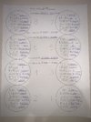
The fixed block is back and much better now now. Naturally it took longer than promised. I’m much happier with it now. Here’s what all the measurements look like now.


IMG_5373.jpeg

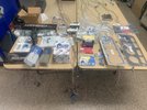
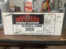
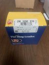
Here’s the new pistons and rings. This set of pistons did not measure out as consistent as the last set, but I was able to assign them to bores that would make up the size difference. Should work well.

IMG_5376.jpeg
IMG_5377.jpeg

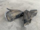
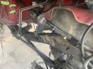
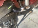
I’ve been slowly playing with wiring and then I got a wild hair and cut out the old motor mounts. I think I will end up cutting out the upper link on the passenger side, as I want to run a three link when I get a new axle. I’d much rather have the A/C compressor down low and out of the way as well.

IMG_5371.jpeg

IMG_5370.jpeg

IMG_5369.jpeg

I ran out of time to clean up the welds. I will fish plate the inside of the frame to strengthen it. That big hole behind the motor mounts likes to cause the frame to bend right there.
 

UNSTUCK

But stuck more often.
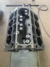
And so it began. Spent too many hours on Saturday building the new engine.

Blocked cleaned up and ready.
IMG_5408.jpeg

Some good parts going in.
IMG_5406.jpeg

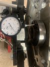
Main and rod bearing clearances were all checked. They were all very consistent between 1.5 and 2 thou.
IMG_5411.jpeg

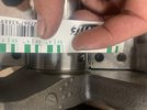
Checking crank end play and run out.
IMG_5412.jpeg

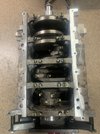
Everything torqued. Bolts with two paint marks indicate that it was torqued to spec and then angle added.
IMG_5416.jpeg

BTR Truck Torquer cam installed with new timing set and dampener.
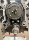
IMG_5417.jpeg

Everything went together great. I’m OCD about taking notes along the way of all my measurements and things like that. But I think I screwed up. The Hastings piston rings may have got me. The top ring has no mark so it can be installed either way. The second ring has the word “up” on one side. These are supposed to be drop in rings but the piston instructions say that the top ring needs to be opened up 40%. The first 3-4 rings that came out of the second ring bag were already facing up. I’d stick them right in their bore and verify end gap. Then right onto the piston. I did this same procedure for each ring. When I got to #7 and put it on the piston I realized it was upside down. I took it back off and flipped it over. The ring for #8 was still in the bag and I noticed it was upside down. I flipped it over, checked it in the bore, installed it, and then installed the piston.
Now I sat there wondering about #6. I couldn’t specifically remember noticing if the ring was facing up. Knowing I wouldn’t sleep, I pulled it out. It was correct.
Well I didn’t sleep anyways. I know the first couple rings came out of the bag facing up and I know the rings for 7 and 8 were facing down. I now know 100% that 6, 7, and 8 are right. I’m second guessing myself at 4 and 5. I guess I just need to pull them and check them.
For me the problem was that the top ring didn’t care which way it went in so I wasn’t checking it. Now I’m worried I didn’t check the lower ring. I probably did……
I will start adding ring orientation to my notes on my next build. 😕
 

UNSTUCK

But stuck more often.
Two steps forward and one step back. I got the front and rear covers in place. The front cover is an LS3 cover without the VVT parts. It came with a seal installed. The rear cover is the stock cover and I installed a new seal in it. I then installed a new GM harmonic balancer. I went with an aftermarket LS1 oil pan. This one looks pretty nice. They sure are hit and miss. Then both oil pan to rear cover bolts pulled out the threads. I hadn’t even put the torque wrench on them yet. Was just pulling all the bolts down evenly. So now the pan needs to come back off and I’ll grab a new rear cover.
 

UNSTUCK

But stuck more often.
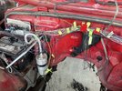
Just a quick update. Ive been working hard on this and slowly making progress. I gutted almost all the wiring in the engine bay to clean it up. I got rid of quite a few wires from the Jeep ECM that are no longer need and kept the ones that will continue to run the dash gauges and a few other items. To me it looks way better and will help fit the GM ECM wiring. The GM ECM will be mounted right under the Jeep ECM. The two will be tied together using one wiring harness, with the hope of looking like a factory install.


IMG_5498.jpeg

The engine is fully assembled now. I hung it in there for a test fit. I will need to notch the passenger side frame to clear the A/C compressor in the factory location. I have all the parts to build a three link, but not sure I really need to. I may just need to limit up travel an inch or so. Still deciding on that. I will need to relocated the accumulator though and figure out new hoses for that.

The goal for this week is to have the engine finished mounted by Saturday.
 
Top