Track bar vs Drag link geometry

DaveB

Long Jeep Fan
Location
Holladay, Utah
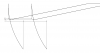
In an attempt to understand the geometry of track bars for my latest project that uses high steer I decided to draw up some drawings to show the relationship between track bar and drag link lengths and geometry. I thought this may be an interesting topic for discussion. The first drawing shows how my project is currently set up, which is a drag link that is longer than the track bar with the start and end points are at the same heights but offset due to real word limitations . As the drawing shows the track bar and the drag link travel in different arcs which means as the axle travels up and down the drag link and track bar don't match the same path so bump steer will happen. The range of travel is limited so it shouldn't be too bad since the arcs don't diverge that much (I hope). The second drawing shows the two bars the same length but offset in x. This setup will not bump steer but is hard to implement exactly for most rigs. The next drawing shows the worst of all situations which is mismatched lengths and mismatched heights. As you can see the arcs are very different and this will bump steer badly. The fourth drawing shows what happens if the track bar frame mount was at the same position as the pitman arm joint in both x and y. The arcs traveled by the track bar and the drag link never change relative to each other so no bump steer, especially if the two were the same length. This option is difficult for most applications. The last picture shows leaf springs where the axle travel is up and down and the drag link wants to go in an arc. The level drag link will still bump steer but nothing like the long drag link that is up high. Hopefully my drawing shows up.
 

Attachments

  • DragLTB.doc
    176.7 KB · Views: 57
Last edited:

B2-Bomber

Guest
Location
SL, UT
as I am currently trying to figure out my crossover steering on mine. I am curious how a person could calculate this for a leaf-sprung front end. even though there is no trac-bar. the drag link length, and how it correlates to bump-steer is still very crucial

I don't want to be driving down the highway, and hit a bump, and have my rig jump into the next lane. nor do I want to be driving and hit the brakes hard, and have the front end dive and crash veer off the road or something
 
Last edited:

I Lean

Mbryson's hairdresser
Vendor
Location
Utah
I agree with almost all your conclusions--except for the one where you say the same length and angle drag link and track bar will still bumpsteer if they're offset. They'll travel the exact same arc, so the bumpsteer would be zero.

To better visualize all you're saying, maybe edit your drawings so it just shows the arcs from the min and max travel lines instead of a whole circle. Then draw a straight horizontal line between the points--the difference in length of those lines is your bumpsteer.
 

DaveB

Long Jeep Fan
Location
Holladay, Utah
I agree with almost all your conclusions--except for the one where you say the same length and angle drag link and track bar will still bumpsteer if they're offset. They'll travel the exact same arc, so the bumpsteer would be zero.

To better visualize all you're saying, maybe edit your drawings so it just shows the arcs from the min and max travel lines instead of a whole circle. Then draw a straight horizontal line between the points--the difference in length of those lines is your bumpsteer.

The reason for the full circles is to show how the arcs aren't the same when the two arcs don't come from a co-planar position in both x and y. The radius is the same but the path traveled is different. Over the limited range of motion of a real suspension the difference in the arcs is very small for the equal length set up as you state but I believe there is some.
 
Last edited:

I Lean

Mbryson's hairdresser
Vendor
Location
Utah
I think I can see what you're saying...the arcs converge toward the bottom, so they don't form "parallel" lines, right? (if there were such a thing as a parallel curved line :) )

I made a little drawing to illustrate my point. These are arbitrary 20" long drag link and track bars, 6" of horizontal separation at the frame side. The arcs show around 12" of total travel. Pick any points along those arcs and measure the horizontal distance--it will always be exactly 6". The arcs do converge as the links get closer to vertical, but the horizontal distance between them is still the same...so no matter where your axle is in its travel, the knuckle is not being turned due to the axle's motion--so, no bumpsteer.
 

Attachments

  • Drag link geometry.png
    Drag link geometry.png
    3.6 KB · Views: 24

Tacoma

Et incurventur ante non
Location
far enough away
Look at the big brain on Stratton!!!

I was about to say a bunch of stuff about angles and length and arcs and all that but it's been covered by the excellent Mr. Lean.
 

UFAB

Well-Known Member
Location
Lehi Ut
Make both as long as possible. Flat as possible and parallel.

No hoaky drop pitman arm or steering arm spacers.

Most of all link designs are application driven.
 

thenag

Registered User
Location
Kearns
as I am currently trying to figure out my crossover steering on mine. I am curious how a person could calculate this for a leaf-sprung front end. even though there is no trac-bar. the drag link length, and how it correlates to bump-steer is still very crucial

On my bronco (leaf sprung) I remember the more parallel the drag link to the ground the better, I had very little bump steer. (no that tie rod is NOT bent I don't know why it looks bent)
dscn0154.jpg

Nathan
 

DaveB

Long Jeep Fan
Location
Holladay, Utah
I think I can see what you're saying...the arcs converge toward the bottom, so they don't form "parallel" lines, right? (if there were such a thing as a parallel curved line :) )

I made a little drawing to illustrate my point. These are arbitrary 20" long drag link and track bars, 6" of horizontal separation at the frame side. The arcs show around 12" of total travel. Pick any points along those arcs and measure the horizontal distance--it will always be exactly 6". The arcs do converge as the links get closer to vertical, but the horizontal distance between them is still the same...so no matter where your axle is in its travel, the knuckle is not being turned due to the axle's motion--so, no bumpsteer.


OK I see what you meant, so I edited the original post. I see how the drawing works as long as the axle stays horizontal but does the argument hold if the axle is not horizontal (bump lifts one side or hole drops one side but not the other) ? It seems to me that in this case the horizontal distance in your drawing isn't the same.
 
Last edited:
R

rockdog

Guest
Make both as long as possible. Flat as possible and parallel.

No hoaky drop pitman arm or steering arm spacers.

Most of all link designs are application driven.[/QUOTE

I agree with Mitch. If you look at stock vehicles with a track bar/panhard bar, they have unequal length track bar and drag link. My 01 f350 with leafs has a factory track bar. It is way shorter than the drag link. It didn't have bump steer from the factory. My opinion is, I think what Carl is kinda(I think) saying. Get em parallel so they a following(somewhat but not exactly) the same arc. Then roll with it.
 

I Lean

Mbryson's hairdresser
Vendor
Location
Utah
OK I see what you meant, so I edited the original post. I see how the drawing works as long as the axle stays horizontal but does the argument hold if the axle is not horizontal (bump lifts one side or hole drops one side but not the other) ? It seems to me that in this case the horizontal distance in your drawing isn't the same.

You're right, if the axle is articulated at all then it throws things off. The good news is, typically any situation that would have the axle at any real angle also is a situation where a little bumpsteer won't be noticed or problematic. :) You're either going slowly crawling, or you're bombing through something rough enough that it's probably throwing you around some anyway. But, to do what you were saying (have them mounted at the same point in X and Y) is pretty much impossible. The axle-end attachment would have to be somewhere in the middle of the steering knuckle, or ball joint, or something else inconveniently placed.
 
Top