General Tech What did you work on Today?

Tonkaman

Well-Known Member
Location
West Jordan
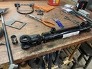
Anyone have a short piece of steel tube with a heavy wall and 1”-1.25” ID? I need like a 4” piece. Any OD works but the heavier the wall, the better.

I just can’t bring myself to drill a hole in some solid bar stock that I have for this specific piece.
How about 1” schedule 40 pipe?
 

glockman

I hate Jeep trucks
Location
Pleasant Grove
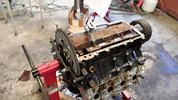
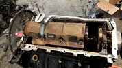
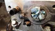
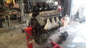
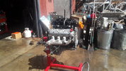
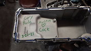
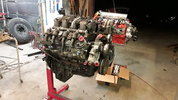
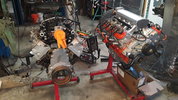
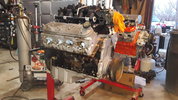
I got my new buggy engine out and Cleaned up. I put on a low clearance Holley oil pan i scored through some horse trading, and removed a broken exhaust manifold bolt that every ls engine I have came across has. View attachment 135854View attachment 135855View attachment 135856View attachment 135857View attachment 135858View attachment 135859View attachment 135860View attachment 135861View attachment 135884View attachment 135885
Here's to hoping Austin is a chick.
Funny story, many of my co-workers are ex navy and many worked on nuclear carriers or subs. The game there I guess is to draw a dick the furthest into a nuclear reactor control panel. Maybe you missed your calling.
 

zmotorsports

Hardcore Gearhead
Vendor
Location
West Haven, UT
And that's where I'm hiding my battery, there's a brace/splash shield that mounts in the area we'll cut and modify to still brace and protect the battery from debris.

View attachment 135877

Looking good.

If I could make one suggestion if you haven't already planned on it. I mounted my battery in the trunk of my '40 Coupe years ago and then worried about access as I had all electric/remote openers for doors and trunk so I added a couple of battery lugs in an inconspicuous location that I could access easily if the battery went dead.

This is what I used and went through the chassis back near the trunk.

They worked great and in the 11 years that I showed and raced the car I only needed to use them once for an emergency. I used them more often to connect a trickle charger to the car between races and/or shows.

Just a suggestion.

Mike
 

zmotorsports

Hardcore Gearhead
Vendor
Location
West Haven, UT
It's been a long couple of weeks and I should have posted this as I've done it but here is a HUGE photo and description dump.

Sorry guys.

I've been working on installing a FASS (Fuel And Air Separation) system on our 2003 Monaco Dynasty on the Roadmaster S-Series chassis for the past couple of weeks. Unfortunately I've only been able to spend an hour here and there on it so it has drug out much longer than anticipated.

I purchased the FASS Titanium system back in October after returning from a gathering with our FMCA friends in Moab as one of them had just replaced their 2nd CAPS pump on their Cummins ISC. Seeing as the ISC and the ISL share the similar CAPS pumps I became a bit nervous/anxious and wanted to build myself in some additional reliability as my coach is racking up miles and I'm sure there is wear being introduced into the fuel system. The ISC and ISL engines are very reliable and great powerplants for mid to large sized diesel pusher RV's and the only area of concern is the CAPS system.

The CAPS pump system is the Cummins Accumulator Pump System that was a modular design. It was the design that Cummins used between the older mechanical fuel injection system used on the 8.3 prior to 1999 and before the HPCR (High Pressure Common Rail) fuel system that Cummins introduced around late 2003 for the 2004 model engines and is still being used today.

I have kept a very close eye on my fuel system over the years and have never had an issue with air intrusion like many fellow RV'ers but I have had to replace the OEM lift pump twice on our coach in the 14 years we've owned it. The OEM lift pump is not a continuous duty lift pump like found on the smaller Cummins B motors in light duty pickup trucks, rather the lift pumps on the ISC and ISL are merely to prime the system prior to starting. They run for a few seconds to build pressure to supply filtered fuel to the supply side of the injection pump. Once the engine fires, the lift pump shuts off and the injection pump pulls fuel using vacuum from the tank to the primary filter, then the lift pump, through the secondary filter and finally to the CAPS injection pump. As you can see this puts a big responsibility of the low pressure side of the CAPS pump to pull not only the 35+ feet from the tank but also through two filters. Add in wear over time that normally takes place and a gasket at the LPM (Lift Pump Manifold) where the lift pump mounts that is notorious for coming loose and leaking and there is a high probability that air can be introduced into the fuel system wreaking havoc on the CAPS injection pump.

I replaced my OEM lift pump when we first purchased the coach back in 2007 with 55k miles on it due to a slight leak that I detected. This was when ULSD was first being introduced as the CAPS system was not designed to run on ULSD and there was a surge of leaking Cummins lift pumps at the gasket as well as the electrical connectors. The lift pumps were the first to leak and create and air intrusion path to the fuel system, other areas such as connections soon followed to develop leaks. However, being under vacuum these leaks went undetected as they usually didn't leak fuel, they just sucked in air creating excessive wear and causing CAPS pump failures. I had replaced my OEM lift pump with an updated Cummins lift pump that was "redesigned" to cope with the ULSD fuel now being used. The coach ran perfectly until around 2014 when I had a stumble at higher RPM's and after extensive troubleshooting I discovered that the small check valve in the OEM lift pump was slightly stuck preventing flow of higher volume of fuel. I again replaced the lift pump with another OEM Cummins pump. The system has run flawlessly ever since and I keep a close eye on it knowing its possible shortcomings of having to draw fuel from such a distance.

After our friends 2nd CAPS failure and seeing a lot of failures popping up on RV forums I opted to build in a means of supplying constant fuel pressure to the CAPS pump as well as some additional filtering or "polishing" while I am at it. The FASS system seemed to be just what I was looking for. Fellow RV'ers have also used the AirDog system which is slightly different in the way it provides the fuel and I have also heard good things about them but ultimately any positive pressure you can give to the fuel on these CAPS engines is going to help immensely. It should also be worth noting that the engine's ECM is mounted to the side of the CAPS module system and utilizes the fuel to cool the ECM so an insufficient fuel flow can both starve the CAPS pump as well as affect the ECM. I have read failures of both over the last while.

As an FYI, most people seem to be mounting the FASS or AirDog pumps in the engine bays at the rear of these coaches in place of the primary filter. This makes for a very quick and easy installation as you simply remove the primary filter and insert the new fuel pump system in its place and wire it up. Many are still pulling through the OEM lift pump which seems to be working fine. I chose to go a different route and mount my FASS up front right next to the fuel tank behind the steer axle and tie into the existing fuel line feeding back to the engine. I have always been more fond of pushing fluids from the source rather than pulling from a distance but maybe that's just from my industrial maintenance background as those who are mounting their pumps in the rear engine bay are working fine without any issues.

I also chose to bypass my OEM lift pump and take it right out of the equation altogether. By doing so I did need to install a "dummy" relay to fool the ECM into thinking the OEM lift pump is still part of the system and avoid throwing any diagnostic trouble codes. The process I chose created a few hurdles but nothing that couldn't be overcome. Like most any mods or repairs on these large coaches, access is the biggest obstacle. Getting to the OEM lift pump to tap into the wiring and disconnect fuel lines took the most time. I also had to drop the starter motor for access which added some time but was well worth it terms of gaining access to perform a nice clean modification that looks as close to OE as possible.

Follow along as I try to document the installation of a FASS fuel pump into our 40' Monaco coach. Prior to beginning I wanted to get some jackstands under the coach and create a bit more space to crawl around.
d201829a71190e8767904edb7e6f480d.jpg


Here is the system I went with. The FASS Titanium TS-D08-165G. Also some assorted NPT to JIC adapters & fittings.
f12f67a00433e06c56f26913dc7b7eba.jpg


47fa7ef307ec8bb06c9826efef51c2b9.jpg


0800c8fa02a4db9e9be7ad883f702f61.jpg


Mounting the pump and filter assembly was the first item to address as space above the fuel tank was not adequate. The surge tank for our Aqua-Hot system also resided right behind the passenger steer tire in the fuel tank bay so after much deliberating I opted to relocate the Aqua-Hot surge tank and mount my FASS assembly in its place.
Aqua-Hot surge tank removed.
18fe0bfc1a3b0423a34744b395e9cb9d.jpg


Area sanded with a DA and repainted with some extreme duty satin black paint.
58f46e41b704cb4e7a0abfb4bc81e705.jpg


Aqua-Hot surge tank relocated nearer to the Aqua-Hot unit after moving the primary and secondary water filters inboard about 2 inches. FYI, this is where the surge tank is mounted on the Executive and Signature models but their storage bags are slightly larger than on the Dynasty model.
b6abe6dcdab57d7a529736a616275ae1.jpg


Stay tuned for much more of the installation....
 

zmotorsports

Hardcore Gearhead
Vendor
Location
West Haven, UT
Next was to design and build the mounting bracketry for the FASS pump and filter assembly. I don’t want to merely bolt to the approx. 12-gage steel sheeting at the front of the fuel tank bay. Partially because of support but also I didn’t want to create a “tinny” sound from the pump being mounted to thin sheet metal.

I decided to build a brace spanning across from the main chassis rail to the outer structural support then just tie into the sheet metal for extra support.

I found a scrap piece of 1.250” x .188” wall square tubing that was about the perfect length.
02e3f0f7c972528ff10997ee74f0a5be.jpg


I don’t like bolting through square tubing without spacers to prevent crushing. In this relatively thick walled tubing I could have been fine but overkill seems to be my theme on projects.
5105c2c039ae0023ef5aa615b4e99f03.jpg


a95cda6174f06860d7439c7bc1e3c572.jpg


522c2dcb2475a48f7f88a80e38fd8362.jpg


Next was to weld the ends that would tie into the chassis rail and outer structure.
31dc61f239b95c812563adbdcb063443.jpg


89682c7d71e3799bce3da5d5c6b22b9a.jpg


Test fit to mark pump placement on the bracket.
3373a8fd8bfe1eebba3bf1b103eff4ce.jpg


Machined a couple of threaded bosses for the pump mount.
8c39e5c84c884e58d4ae84935bd1a855.jpg


e81c0204edcee61fee3d0d68d3e30e0a.jpg


c4d1613875a7fd61ca48f6cfb12be0a9.jpg


Mounting bracket nearly completed and prepped for paint.
1f0e5f397a3248ca93e40eb9dd92959d.jpg


ff7295356f2a988994c1729fd21c6456.jpg


8bf2758ee833c36035d95a28aaa7e887.jpg


Corresponding mounting plate being drilled with the same bolt pattern where a rubber isolator will be sandwiched between the pump and mounting bracket.
155300a3f2d31f9e7cba5bb59ad2bf8e.jpg


Painted and ready for final installation.
a378b2b1d975ceda439098e67d62f184.jpg


Bracket installed.
8d35f4cc1ab0631ff997cfcaa2408f95.jpg


More to follow.....
 

zmotorsports

Hardcore Gearhead
Vendor
Location
West Haven, UT
Prepping the pump by installing fittings.

1/2” NPT to a -10 JIC elbow. This will be the supply from the tank.
794296dafdb635db6805b24771193863.jpg


1/2” NPT to -10 JIC straight (black fitting) for the pressurized and filtered fuel leaving the pump manifold. The silver fitting is a 1/2” NPT to a -8 JIC which is the FASS return to the tank. This will run to a bung in the opposite side of the tank.
3d2ffc877b00a45b0c8dd9ee26ce86dd.jpg


Pump and manifold assembly fastened to the mounting bracket.
6b24ed0e606f1033a7d173575035f178.jpg


04069d895426db37570877b8fa22d516.jpg


This “T” will be where the return line connects.
bb432cd104ebca03540ed5f525bdd945.jpg


I opted to cover the return line with some abrasion covering to provide a bit more protection to the hose as well as to hide the bright blue hose and make it appear more OE looking. The best mods are hidden in plain sight.
f45b5822cb273a45bfeae240e2cb5fd2.jpg


Return line completed.
f086155cfe1a2183a1f715bc68882616.jpg


Return line installed and connected at the driver’s side of the tank and to the FASS manifold assembly.
4bedf225bdd647fc9ad57b79239ef99c.jpg


I had a couple of new 5/8” fuel lines made up with -10 female JIC connectors crimped on at my local hose supply house. One hose was 32” in length and went from the FASS outlet to the original hose feeding back to the rear of the coach. I remove the original hose from the tank and joined them with a -10 JIC male to male union. I then connected the 40” hose from the tank port to the inlet side of the FASS manifold.
ee39af2f7661dc1edef1c967da5d326e.jpg


Hoses done and filters installed. These will be easily accessed for filter servicing.
ad126d5b2d18660e568fe442f35a58c6.jpg


More to follow.....
 

zmotorsports

Hardcore Gearhead
Vendor
Location
West Haven, UT
Moving to the rear engine bay.

Seeing as how access to my original secondary filter was limited, I opted to remove my primary filter and relocate my old secondary filter to its location. This will provide a third filter in the fuel system and just before the CAPS pump. Probably overkill.

This is also where I deviated from most other people’s installation. I identified the hose on the right in the photo as the original feed from the tank. This is now the supply hose from the FASS pump assembly.

The hose on the left in the photo used to go from the primary filter to the OEM lift pump. I chose to remove the hose at the lift pump and connect it directly to the CAPS pump inlet. This allowed me to remove the other hoses completely from the coach and thus bypassing the OEM lift pump.
7eac56cd02a3d6cf3d0d941da88a400b.jpg


Original secondary filter head and mount which will be mounted under the left rear run box in place of the primary filter.
c9cb5923ad8a9b97e51dd6ba12082098.jpg


The filter head has a metric plug at the top. I purchased a 10mm x 1.0 to 1/8” NPT adapter and a 1/8” NPT “T” fitting.
41ecba776f76d5db35c2cfa523b6fcb3.jpg


221750ba505bcf18a9f51f4a778177ac.jpg


Filter head installed. This will be filter #3 in the system. I also installed a liquid filled 1.5” diameter fuel pressure gauge and a sending unit that will support a cockpit mounted fuel pressure gauge. This pressure will represent what is being seen at the CAPS pump and provide me with data to know what my pressure is at load as well as monitor when my filters will be in need of servicing.
a1329a8abd3618ea5446ac5bbb7c9b28.jpg


Hoses connected.
b4c1b170114683d81a9c61601258866c.jpg


Filter installed.
f61fbfc4be48e4397c04d23111173aa7.jpg


WIF (Water In Fuel) sensor wire extended, covered in convoluted casing to match OEM wiring and connected to the sensor at the bottom of the filter.
e65cff22d17c37c0aff34c6bce90ae77.jpg


More to follow......
 

zmotorsports

Hardcore Gearhead
Vendor
Location
West Haven, UT
Next was to bypass the OEM lift pump.

I removed the hoses and capped off the inlet and outlet of the LPM (Lift Pump Manifold) then extended the wiring for the lift pump. The inlet hose going to the OEM lift pump now goes directly to the CAPS inlet. This portion of the entire project was hands down the most difficult part because of how limited the access is to the OEM lift pump.
cf0ef7792a20eea9de02de6386f334dc.jpg


b7339495c8e2e629b2a98ec87cfd13af.jpg


To fool the ECM into thinking the OEM lift pump is still connected a small load must be placed on the circuit. Many are just using an auxiliary relay such as for lighting and putting female connectors on the wires and connecting the relay then zip-tying the relay to the wiring harness near the OEM lift pump. This works perfectly but in the event that the relay ever fails it will require squeezing back into the area where the OEM lift pump resides and not easily accessed on our coach. I chose to extend the wiring in abrasion covering back to the right rear run panel and place the labeled relay inside of the enclosure.

I also prefer to use OE style connectors when possible so I spent a few bucks more and purchased a relay and wiring harness as an assembly. This is the NAPA relay made by Echlin that I used.
7b81fc7db276df72b00a76a31fb33578.jpg


Seeing as how there is no load on the relay and I only needed the control side I removed the non needed wires altogether. I kept the wires going to pins 85 and 86 which are the coil in the relay.
3f5a4b9c78a2ba2a492ab934b476f34f.jpg


15fed26b4eb7d1e414a92bc9c226f9a2.jpg


Labeled the relay.
2c4c3b061f33888bee7f84987a727447.jpg


Mounted the relay.
6d0f6cfd3f5b5afa93b68a060b15d218.jpg


b764c3472820578928053419a760fab4.jpg


Reinstalled the cover back on the right rear run box.
7b9227d0c566722c027276dfef25abe2.jpg


That is as far as I’ve made it so far. All that is left is the wiring to the FASS pump and she’s ready to fire.

Thanks for looking.
 

zmotorsports

Hardcore Gearhead
Vendor
Location
West Haven, UT
Drilled & tapped the exhaust manifold to accept the K-style pyrometer probe.
c25cf5a8928c8a270574f8901d80449c.jpg


Secured wiring away from the exhaust heat.
3f87d1392be972ed783b1acbe2815b25.jpg


Ran the wiring for the fuel pressure sending unit into the left rear run panel and tie into the wiring in which I run through the chassis and up to the cockpit. Encased it in abrasion coating to appear OE.
ec09ca958725b99570f231cd2e99c055.jpg


96aebca08963d0fb45307ace6334ef20.jpg


Machine a couple of aluminum standoffs to mount the pyrometer extension module.
5ea5152b1b8cf84b8d336814f6bb8e77.jpg


Extension module mounted and wires connected.
10f5e6be9b04539cb3023ded502656dd.jpg


Labeled.
c338ecad780b66f5a901c95236829b3e.jpg


Left rear run box buttoned up and everything at the rear is now completed.
3007a353eddb0a237bd380500bb9b235.jpg


Thanks for looking.
 

zmotorsports

Hardcore Gearhead
Vendor
Location
West Haven, UT
I ran the wiring into the front run box which is on the driver’s side just ahead of the steer axle.

I used the wiring harness that came with the FASS fuel pump and installed the relay on the side of the run box and tapped into an unused “key on” power terminal with a 3 amp fuse.
5f4f442295fd57e97360718735612f0c.jpg


a00544a3fc1c539913c863622a9c6851.jpg


Battery feed side of the relay tapped off power feeding the run box fuse panels through a 10 amp fuse and everything labeled.
34aab97509cc50a2f6635c3873e02ffc.jpg


After double checking the wiring and connections at the run box and at the pump I loosened the secondary filter/water separator at the FASS pump and prepared for priming.

Turned the key on and as soon as the pump tone changed I hurried and tightened the secondary filter. Only had a very small amount seep out before I was able to get it tight.

I could hear bubbles and air being being forced out through the return line and into the fuel tank but the entire system was drained so I figured it would take a minute or so, plus this gave me a chance to check all hose connections as well.

After cycling the key again I cranked it and she fired right up. It stumbled ever so slightly as there was air between the third filter and the CAPS injection pump that had to forced through and returned to the tank but it smoothed right out and idled great.

I let it run for several minutes before shutting down and letting it sit while I swept up and put tools away.

After about fifteen minutes I restarted and it fired right about like it always has but I noticed right away it idled smoother. I just thought maybe it was the placebo affect but my son stopped by and I asked him what he thought. His first comment was “it’s idling smoother”. I then figured maybe it actually is and not just in my head.

All in all a great modification and after a few more items on my gauge panel and wiring I can take her out for a spin.

That concludes the FASS installation in our 2003 Monaco Dynasty. Only item remaining is to fabricate a gauge console to add my gauges to the cockpit and wire them in.

Thanks for looking.

Mike
 

Bart

Registered User
Location
Arm Utah
Excellent project, execution, and write up as always. Love the preventative maintenance that path you always take. Concept is much more complicated but similar to the fuel/water separators on boats., sans the pump.
 
Top