General Tech What did you work on Today?

RockChucker

Well-Known Member
Location
Highland
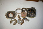
Looked into my steering issue that surfaced in Sand Hollow last weekend. This kept from making the Hanging Tree run today. At least I know what the problem is now...
View attachment 137972
Do your knuckles, cylinder and box hit the stops/max travel at the same time? That failure makes me think that the box is at the limits of travel and at a hard stop but the hydro cylinder still has more to go and is basically twisting the sector shaft. Just some food for thought. I don't think you necessarily need to ditch the hydro assist, unless you're after more steering force at the tire.
 

Pile of parts

Well-Known Member
Location
South Jordan
Do your knuckles, cylinder and box hit the stops/max travel at the same time? That failure makes me think that the box is at the limits of travel and at a hard stop but the hydro cylinder still has more to go and is basically twisting the sector shaft. Just some food for thought. I don't think you necessarily need to ditch the hydro assist, unless you're after more steering force at the tire.
That's a good thought! I'll definitely look into it. It hadn't really crossed my mind because there was a certain incident on the trail where, I'm pretty sure, the damage occurred. It was not in an area where I would have expected a problem. I was coming down off a short, steep section on an angle and the front driver tire kind of wedged, for an instant, in a notch (similar motion to crossing the Golden Crack but smaller scale). This was the first time I have ever had the steering wheel jerk out of my hands. I don't recall hearing any noises when it broke but steering, left or back to straight from left, certainly became a challenge. You could be on to something with unequal throw of the different components.
 

DaveB

Long Jeep Fan
Location
Holladay, Utah
I've been working on a couple of winches. Both are Warns, an M8000 my son found off of a wrecked Jeep and the fu-barred 9.5 ti from Cruiser Outfitter. The 8000 didn't look like it was ever used much but must have been driven a lot on salty roads. After a lot of cleaning I got the winch working by manually driving the armature and field lines. The relay pack is messed up with two bad relays, missing cables and relay tie bars. The relays should have been sealed but the one I took apart was corroded inside. I'll have to round up some parts to finish this one off.
The 9.5ti took some serious work to get the corroded and broken bolts out of the housings. I soaked the bolts with kroil then tried the weld on a nut trick. The weld trick worked on one of the bolts but the rest just kept breaking off the bolts. Had to resort to drilling out the bolts. This was tricky due to the curved shape of the housings and having to drill about 1.5" through a 3/8 bolt while staying centered.
Got them out and now I am working on putting it back together. I would like to fire the engineer that designed the back cover to the motor. The wires for the thermo switch are directly in line with brackets that hold the brushes. You have to put it on out of position then rotate the cover into the final position. When the winch was taken apart the thermo switch mount broke off so I've had to try and figure out how it was mounted from the factory. I haven't been able to find any images that show how the switch mounts.Here is what one relay looks like inside, I'm thinking I should probably replace all 4.

IMGP5531.JPG
 

cruiseroutfit

Cruizah!
Moderator
Vendor
Location
Sandy, Ut
That thermo switch connector was popped apart previous to the disassembly as I recall. That as on our hitlist to repair as the light wasn't working. I actually planned to just ditch the overheat light after finding out the connector was messed up. You're becoming quite the Warn guru.

I would like to shoot the engineer that spec'ed that material for the 9.5ti housing and covers, it's just a nasty aluminum and blistered up badly. Newer models have gone away from that or at least use a better coating.
 

RockChucker

Well-Known Member
Location
Highland
That's a good thought! I'll definitely look into it. It hadn't really crossed my mind because there was a certain incident on the trail where, I'm pretty sure, the damage occurred. It was not in an area where I would have expected a problem. I was coming down off a short, steep section on an angle and the front driver tire kind of wedged, for an instant, in a notch (similar motion to crossing the Golden Crack but smaller scale). This was the first time I have ever had the steering wheel jerk out of my hands. I don't recall hearing any noises when it broke but steering, left or back to straight from left, certainly became a challenge. You could be on to something with unequal throw of the different components.
That is definitely a scenario that could have caused this too. The oem hydraulic control valve integrated into the steering gear has pretty small orfices. When you have an event like that, the box could hydro lock due to the low flow capability of the valve and things could break inside. That is part of the reason I built my steering the way I did, no fluid at all in the box. External control valve and hydro cylinder are the power. The manual converted steering gear is only there for mechanical feedback in the hydraulic control system
 
Last edited:

JeeperG

Well-Known Member
Location
Riverdale
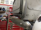
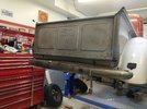
Started getting the rear bumper brackets shortened up a bit, the stock location of the bumper is way too far out, potential to take your shin out, out. I like this look better, cleans up the rear of these things a lot, will also add some roll pan/filler panel stuff back there to clean up the empty voids, then on to the front bumper(s)

Also I haven't decided if I want to add more brake/turn signal LED strips to the section between the tailgate and bumper? I have the chevron LED's in the fenders and some little round LED's that cap off the end of the bed rolls.

PXL_20210606_141426813.jpg

PXL_20210606_141438721.jpg
 

zmotorsports

Hardcore Gearhead
Vendor
Location
West Haven, UT
Over the past couple of evenings I was able to complete a few small jobs.

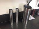
I've had new polished stainless steel exhaust tips sitting on my workbench for a few weeks now to replace the chrome exhaust tips on our coach that were starting to corrode. I had to machine a reducer for the generator exhaust that was 1.5" diameter to slip inside of the 1.75" ID polished stainless steel tips that I purchased. I also had a hard time finding a 5" inlet/outlet exhaust with rolled lip for the engine. Everyone is selling those ridiculous tips like 5" inlet to 7+ inch outlet. May as well rig up a 55-gallon drum to the tip.

ex1.JPG

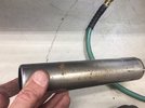
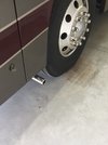
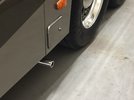
This was the Aqua-Hot exhaust pipe that was just ahead of the street side drive tire. Steel wool would no longer clean these up to my satisfaction but for chrome they held up extremely well for 14 years and over 80k miles.
ex2.jpg

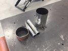
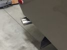
All three tips removed. I also had to cut back the 5" engine exhaust a bit as the new polished stainless steel tip was a few inches longer in length.
ex3.JPG

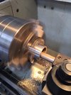
Machining a step reducer to go from the 1.5" generator exhaust to the 1.75" stainless steel tip.
ex4.JPG

ex5.JPG

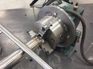
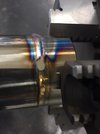
I used my weld positioner to weld the tip to the reducer.
ex6.JPG

ex7.jpg

ex8.jpg

ex9.JPG

More to follow.
 

zmotorsports

Hardcore Gearhead
Vendor
Location
West Haven, UT
Installed/completed pictures.


Generator exhaust tip, just ahead of the street side steer tire. This is the one that I had to machine the reducer for.
ex10.JPG

Aqua-Hot exhaust tip, just forward of the street side drive tire. This 1.75" tip slipped right over the 1.75" exhaust pipe.
ex11.JPG


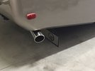
Engine exhaust exit at rear of curb side.
ex12.JPG

I positioned this tip outward about 2" more than the previous tip. With the old tip being right at the body line I think it looks better slightly protruding from the body.
ex13.JPG


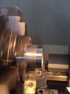
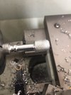
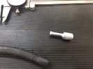
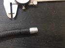
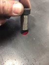
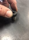
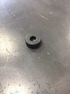
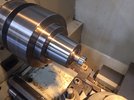
I had a small 1/4" hose to plug and I didn't want to merely stuff a bolt or something in it and I already had chips on the lathe so I knocked out a small knurled plug for it.
fuel1.JPG

fuel2.jpg

No one will ever see this but I still think it looks better than just stuffing something in the hole to plug it.
fuel3.jpg

Thanks for looking.

Mike
 

zmotorsports

Hardcore Gearhead
Vendor
Location
West Haven, UT
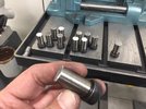
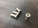
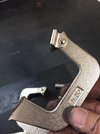
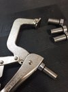
Lastly, before closing up the shop last night I started working on a few new clamps for my welding/fixturing table. I picked up four inexpensive Vise Grip style locking clamps to compliment my "F" style clamps that I modified last year. I picked up some 5/8" shoulder bolts to use as the bases but also some extra ones to act as guides for alignment as I am clamping things down. These will just drop into the 5/8" holes in my table when needed.

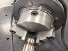
I cut the threads off, touched them up on the disc/belt sander and then turned and faced four of them to remove the knurls as well as the coating in preparation for welding to the clamps.
clamp1.JPG

clamp2.JPG

clamp3.JPG

clamp4.JPG

clamp5.JPG

clamp6.JPG

clamp7.JPG

clamp8.JPG
 

Herzog

somewhat damaged
Admin
Location
Wyoming
I have a friends project buggy in my shop that I'm finishing up for him... build thread to come later.

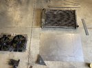
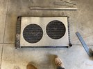
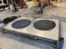
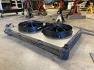
I ordered a nice set of radiator fans from summit machine, what I got was not exactly what I thought I was gonna get dimension wise so I considered sending it back for a different one... but I came to the conclusion that no fan shroud was probably going to be exactly what I need for this so I ended up making my own and using the nice Spal fans with it from the other shroud. Turned out better than I thought it would.

D369FED2-A8C2-41C8-86EF-CDED06078861_1_105_c.jpeg

E0A48A29-4377-4F65-A658-B253E8EDB138_1_105_c.jpeg

6D28C31E-B200-4289-AEEC-1BBEE5E4CDD8_1_105_c.jpeg
78385FEE-781A-4E4F-BD79-0F60746DBEB3_1_102_o.jpeg
 

Vonski

nothing to see here...
Location
Payson, Utah
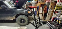
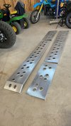
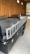
Until today, I haven’t had time to touch my ramp/side-board project in weeks. To make sure they don’t walk off, they get locked to the stake pockets with clamshell type padlocks. Not an impenetrable setup, but would slow the process down a bunch. 🤷‍♂️
 

Attachments

  • 274E4A2E-E31E-4266-BC13-21FBDA7A1BBD.jpeg
    274E4A2E-E31E-4266-BC13-21FBDA7A1BBD.jpeg
    226.6 KB · Views: 27
  • 419DCA6B-94AE-4396-A5E0-3FC1FBE1B790.jpeg
    419DCA6B-94AE-4396-A5E0-3FC1FBE1B790.jpeg
    278.4 KB · Views: 27

zmotorsports

Hardcore Gearhead
Vendor
Location
West Haven, UT
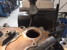
I had a small machining project come through my shop door the other night from a fellow forum member who is building a rock buggy. He is adding an ORD underdrive to his NP205 and needed the NP205's smaller 80mm input bearing bore machined out to accommodate a 90mm input bearing.

Taking some initial measurements of the bearing and determining a target diameter to bore the case to. The bearing measured 3.5425". For interference fits I generally use a .001" per inch of bore formula but where this didn't need to be a complete press fit and just needed to be snug I figured I would shoot for approx. .0005"-.0008" interference fit. This would give me a target bore of approx. 3.5417". I set my bore gauge to 3.5415" which would be .001" under the bearing diameter but I would try to come in on the high side of that by a few tenths.
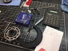
np1.JPG


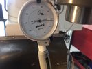
Setting up the case on the mill table. I used a center finder to get it close then swapped in my Blake coaxial tester to dial it in. I was able to get it to about a thou out.
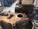
np2.JPG


np3.JPG


Swapped over to my 3" Criterion boring head with my new Mesa insert attachment. It has been a while since I bored a precise hole so I took some preliminary measurements to get my feel back on my boring head.
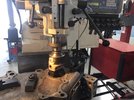
np4.JPG


Landed at .0002" over my target.
np5.JPG


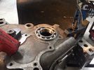
The bearing required a slight tap to fully seat so a perfect fit for the application.
np6.JPG


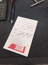
Final notes as I tracked my numbers. Increasing by .050" at a time to get my feel back for my Criterion boring head. I was landing at approx. .0502" to .051" per pass. I am certain this has to do more with where I lined the marks up on the boring head vs. the boring bars actual accuracy.
np7.jpg


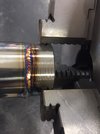
Thanks for looking.

Mike
 
Last edited:
Top