STAG
On my grind
- Location
- Pleasant Grove
I wanted to add a clean relay system for some aftermarket switches on the 12v system of my Gladiator. I have one of the 6-switch pods on my dash and it comes with a relay/fuse box. The circuits are wired directly to the battery but it does come with an extra wire that is a ‘trigger’ wire that activates the system when key-on power is applied, that way the switches that have backlights don’t drain your battery as if they were wired directly to the battery terminals.
This wire here, circled in green, is the key-on trigger wire.
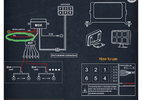
I needed to locate a power source for this wire. I wouldn’t be surprised if Jeep includes a stubbed wire meant specifically for this purpose, but I haven’t researched that at all so I found my own.
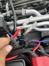
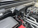
I opened up the cover to my underhood fuse panel and using a test light I found a fuse that is only powered when key-on. The one I went with was fuse F52, which in my case is the cigarette lighter plug. You may be aware, I actually eliminated my cigarette lighter outlet when I installed the Mopar trailer brake controller. Perfect for me but it would also work even if you still have your cigarette lighter outlet. I’m routing the wiring through a relay, so the additional draw on the cigarette outlet circuit will only be milliamps, so I’m not worried in the slightest.
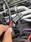
I removed the fuse panel and using test equipment I verified which pin was the correct circuit for fuse F52, and it’s this pink/orange wire, circled here in red.
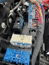
First thing first, remove the blue retainer clip by sliding it to the side, just like the panties of your high school girlfriend.
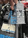
Using care, and a sharp razor blade, I cut back some of the factory fabric electrical tape.
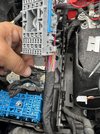
Using a sharp tool, in my case the probe of my test light, push the retaining clip that holds the socket for the pink/orange wire
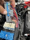
I then cut back about 3/8” of insulation right behind the pin socket
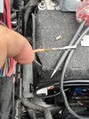
Found some yellow wire, and added it to the exposed area of the pink/orange wire and soldered it in place
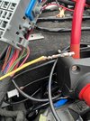
And added heat shrink
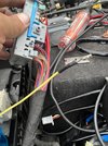
Then, reinstall the socket back in the correct location, and rewrap the harness with fabric electrical tape, leaving the new wire stubbed out of the fuse panel assembly.
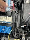
Add the plastic housing back to the back of the harness socket and reassemble the fuse panel.
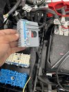
To be continued;
This wire here, circled in green, is the key-on trigger wire.

I needed to locate a power source for this wire. I wouldn’t be surprised if Jeep includes a stubbed wire meant specifically for this purpose, but I haven’t researched that at all so I found my own.
I opened up the cover to my underhood fuse panel and using a test light I found a fuse that is only powered when key-on. The one I went with was fuse F52, which in my case is the cigarette lighter plug. You may be aware, I actually eliminated my cigarette lighter outlet when I installed the Mopar trailer brake controller. Perfect for me
I removed the fuse panel and using test equipment I verified which pin was the correct circuit for fuse F52, and it’s this pink/orange wire, circled here in red.

First thing first, remove the blue retainer clip by sliding it to the side, just like the panties of your high school girlfriend.

Using care, and a sharp razor blade, I cut back some of the factory fabric electrical tape.

Using a sharp tool, in my case the probe of my test light, push the retaining clip that holds the socket for the pink/orange wire

I then cut back about 3/8” of insulation right behind the pin socket

Found some yellow wire, and added it to the exposed area of the pink/orange wire and soldered it in place

And added heat shrink

Then, reinstall the socket back in the correct location, and rewrap the harness with fabric electrical tape, leaving the new wire stubbed out of the fuse panel assembly.

Add the plastic housing back to the back of the harness socket and reassemble the fuse panel.

To be continued;

