I decided to take care of some lingering issues with my Land Cruiser UZJ100, by making it less complex and refined—in the form of a solid front axle.
A little back story: a couple years back we acquired a ’93 80 series Land Cruiser, and fell in love with most aspects of it. The failings of that truck are the lack of power, and associated terrible fuel mileage. So I started looking at wrecked vehicles to be a drivetrain donor to do a V8 swap. While I searched, I realized how much work that swap would be (and the type of work I do not enjoy)…but I also came across a 2002 100 series, which already comes with a V8. It wouldn’t be as powerful as the GM V8’s I was originally looking at, but still a nice improvement over the I6.
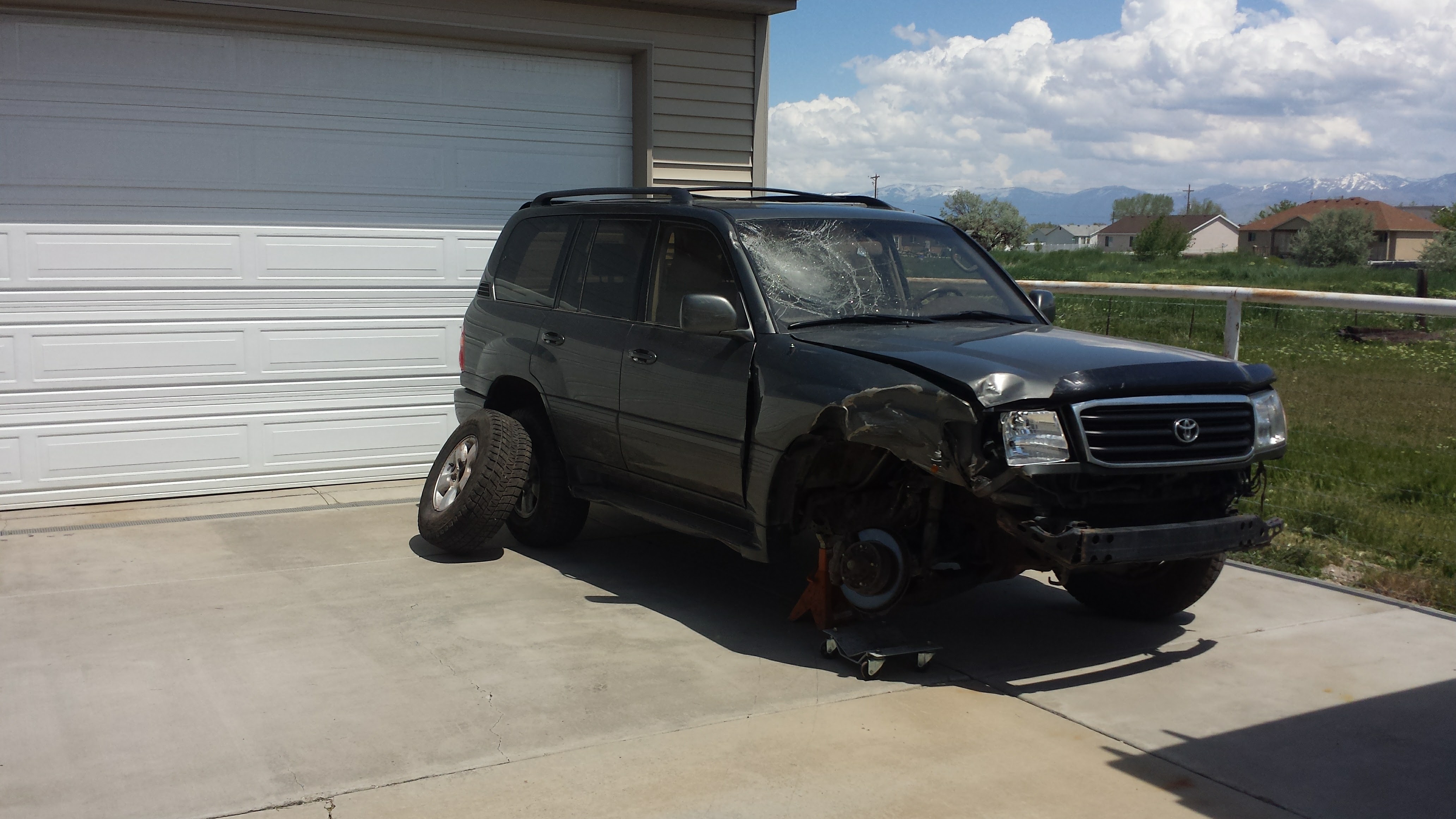
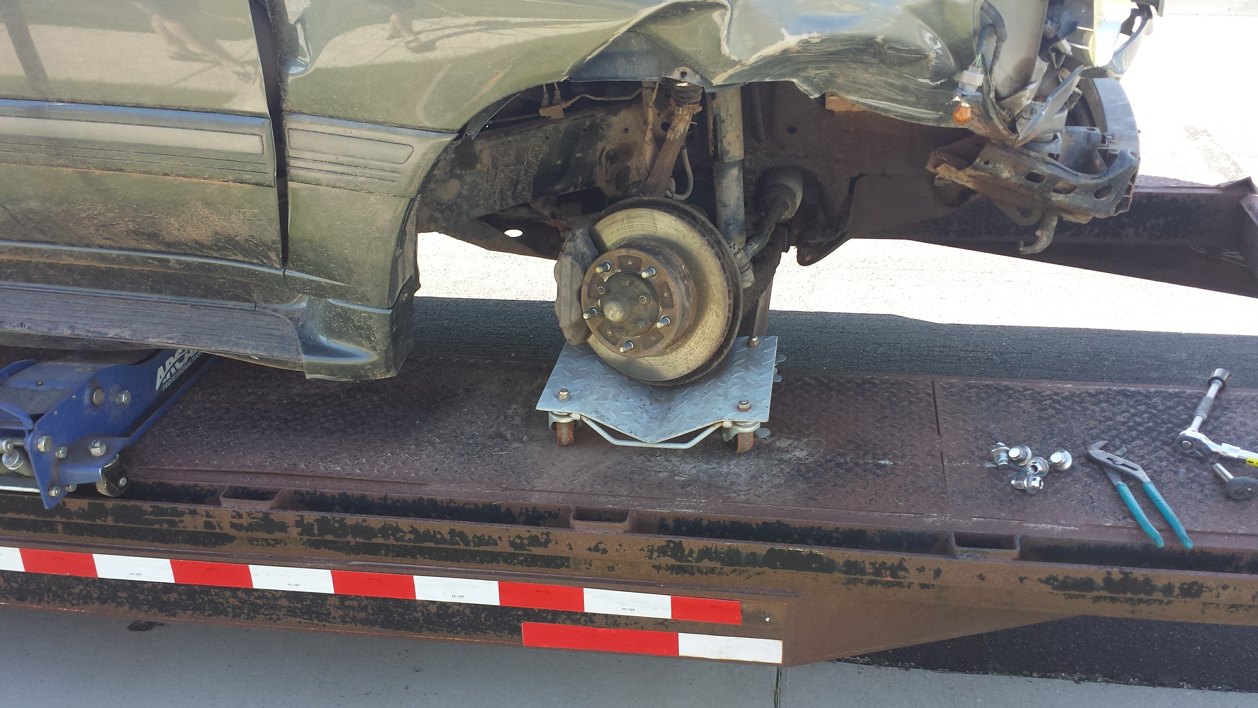
So…I got the 100 for a good deal, I thought. The repairs (naturally) cost more than I was hoping, so my “good deal” at first wasn’t so good in the end, but still OK. I replaced the spindle, upper and lower control arms, fender, hood, headlight, bumper, valence, and had the A-pillar fixed along with the new paint and windshield. The frame was also straightened…as much as it could be. The body shop that was doing the work couldn’t get it quite straight, and bent their frame rack trying.
So…with the frame not-quite-straight, my alignment was always just a bit off. There was some negative camber on the passenger-front, the caster was near zero and the wheelbase was shorter on that side. Some of that could have been remedied with some adjustable upper arms, but overall my wife and I were just not happy with how well it drove. I can fix it!
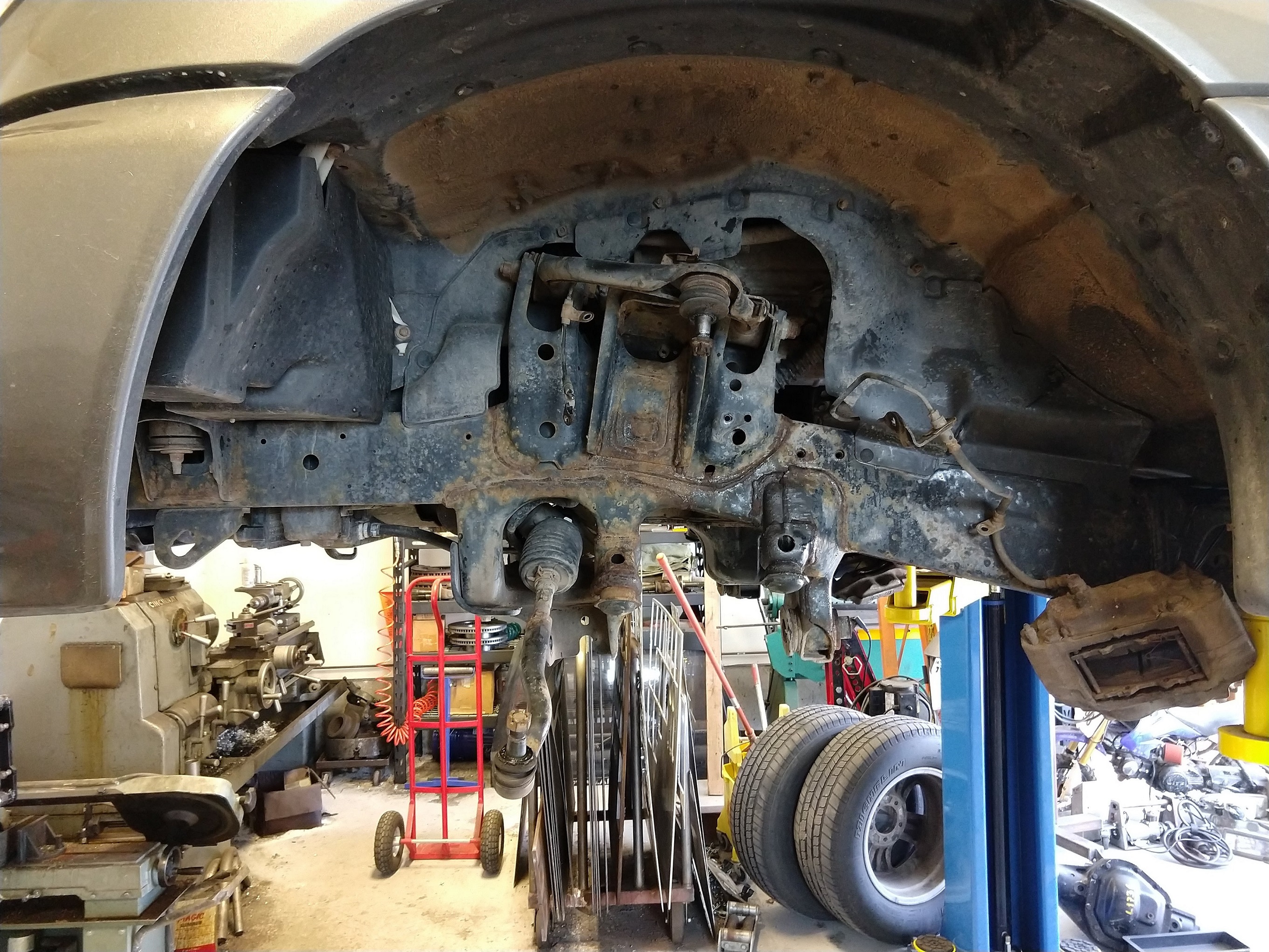
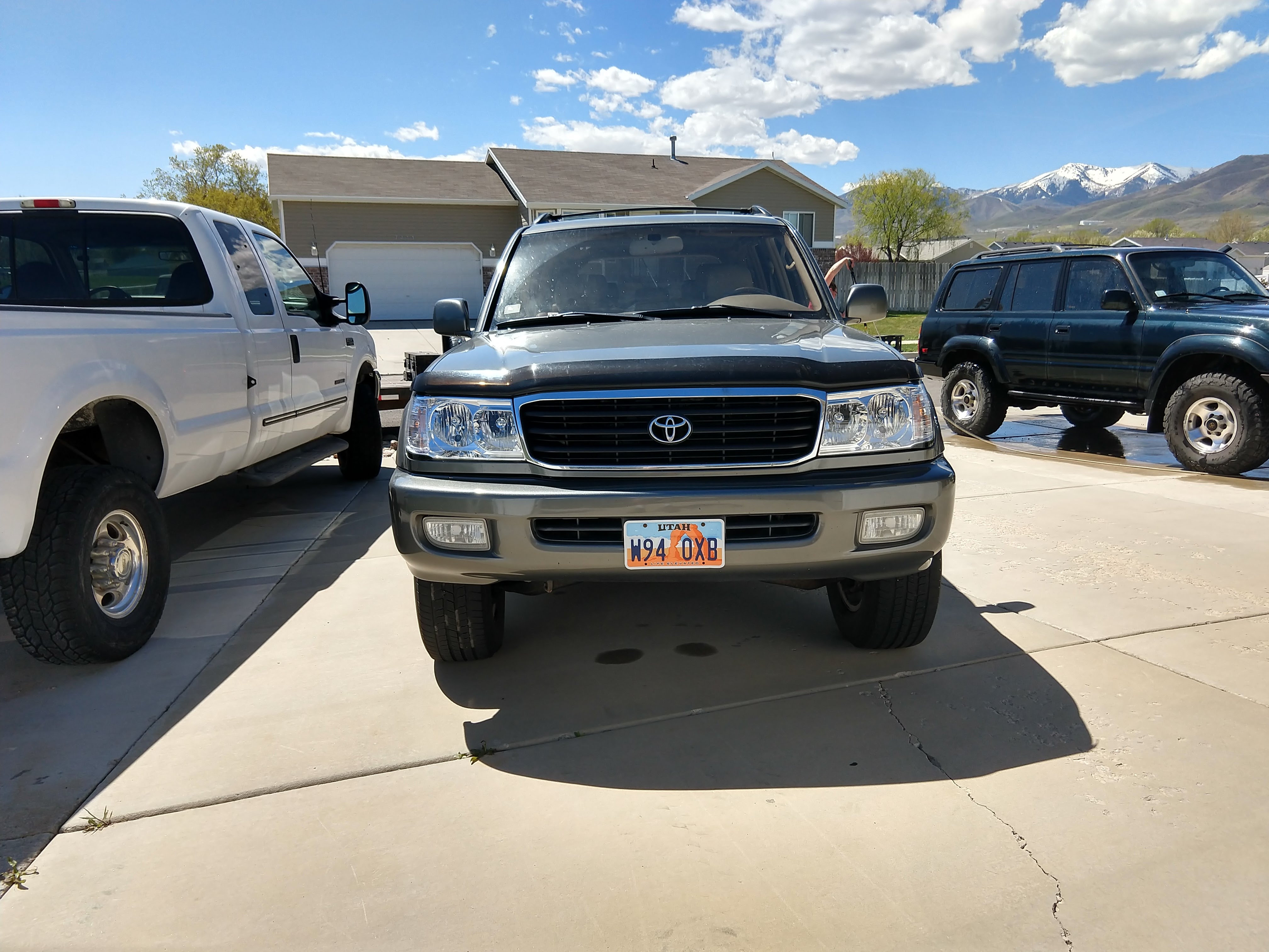
Here’s the “before”. 30mm rear spring spacer, torsion bars cranked to match, 18” 200 series wheels.
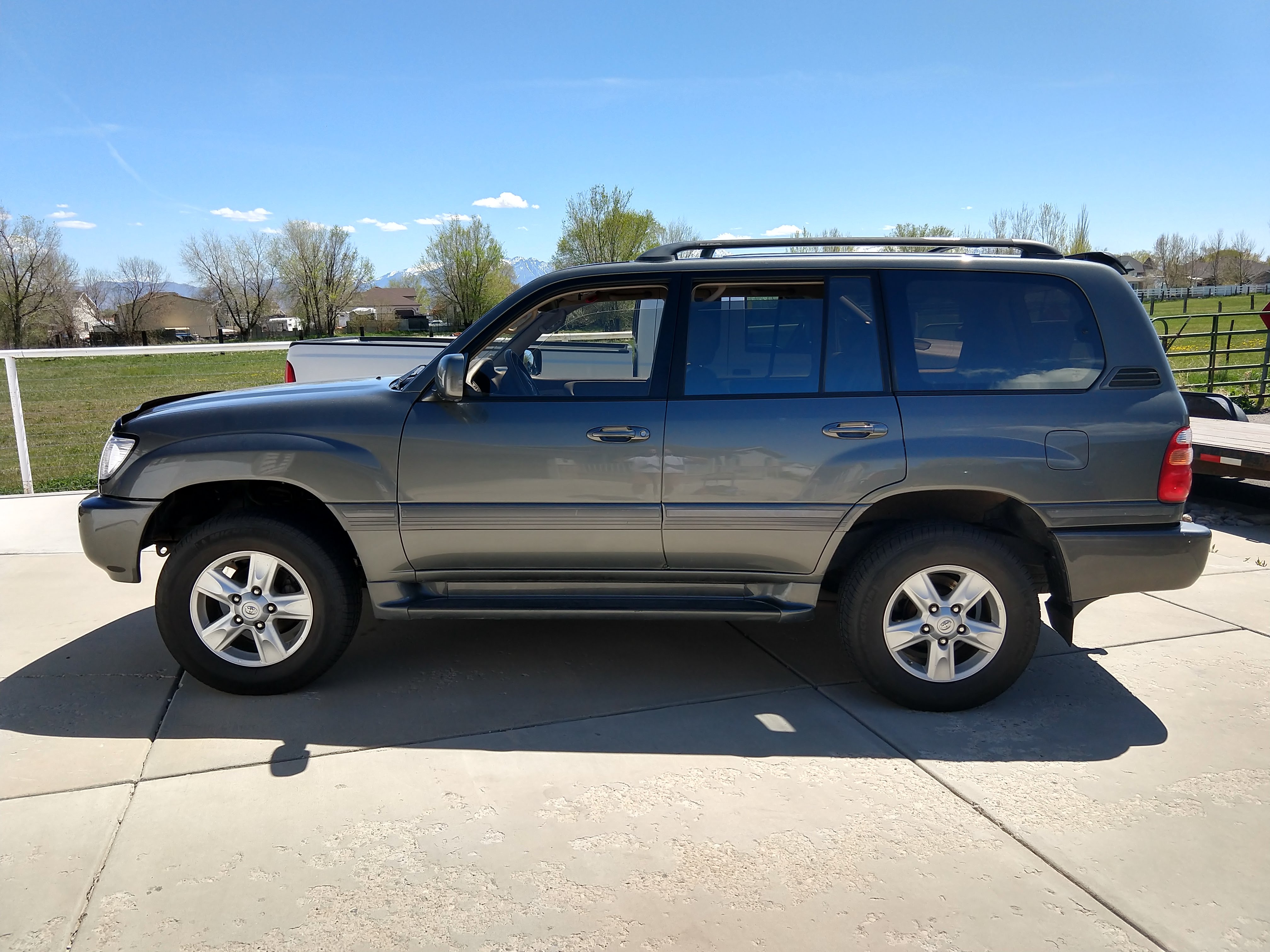
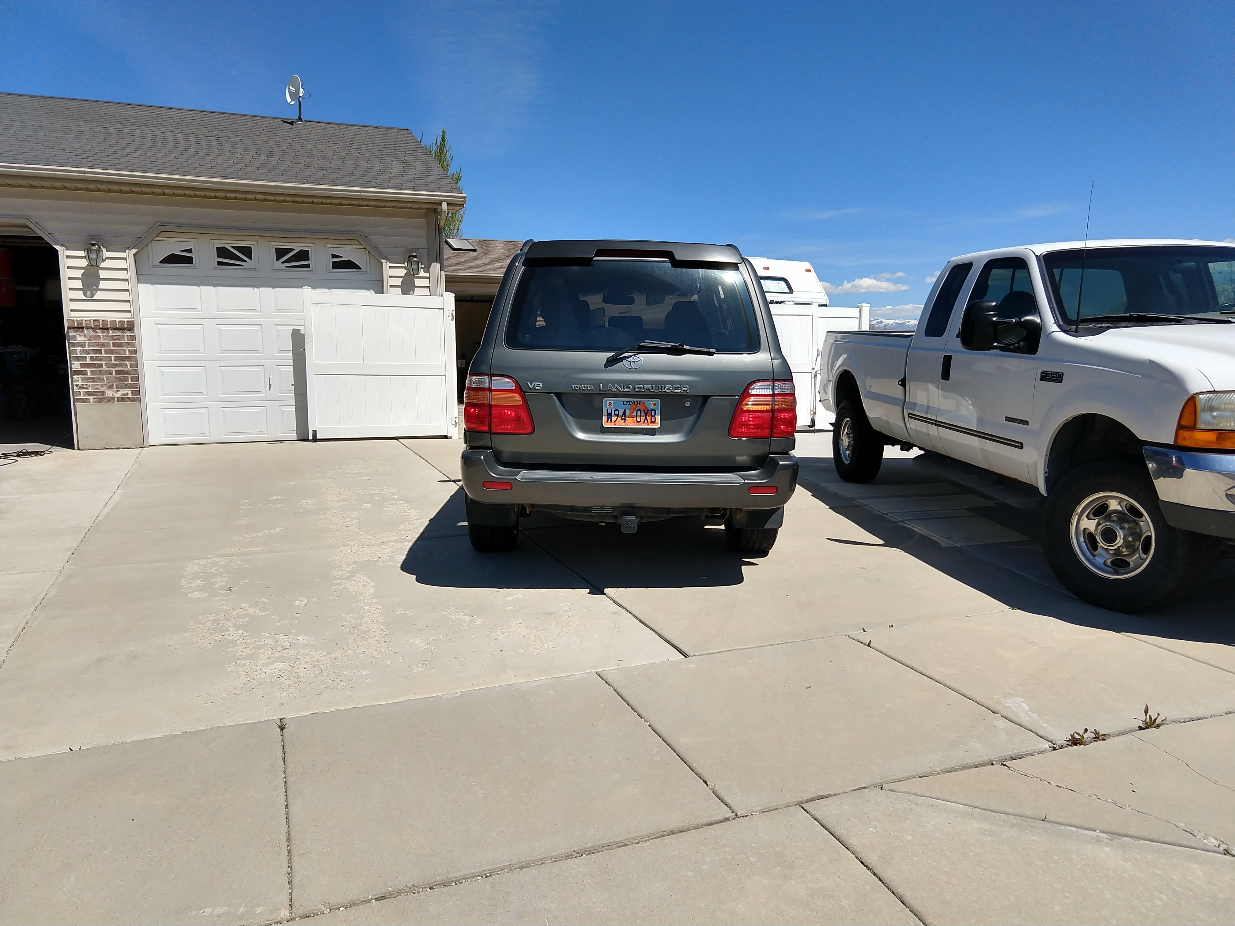
You can spy my beloved 80 in the background here.
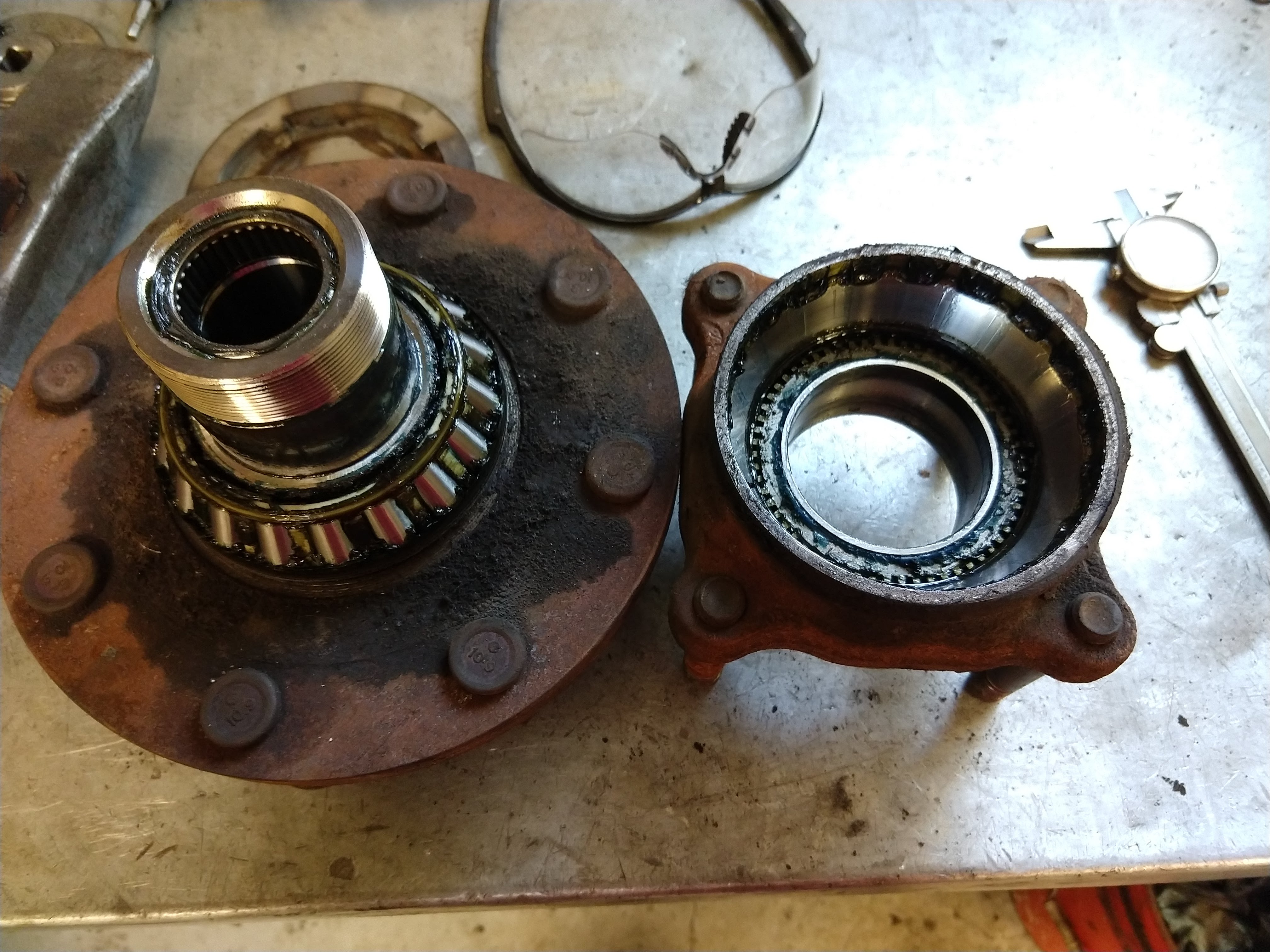
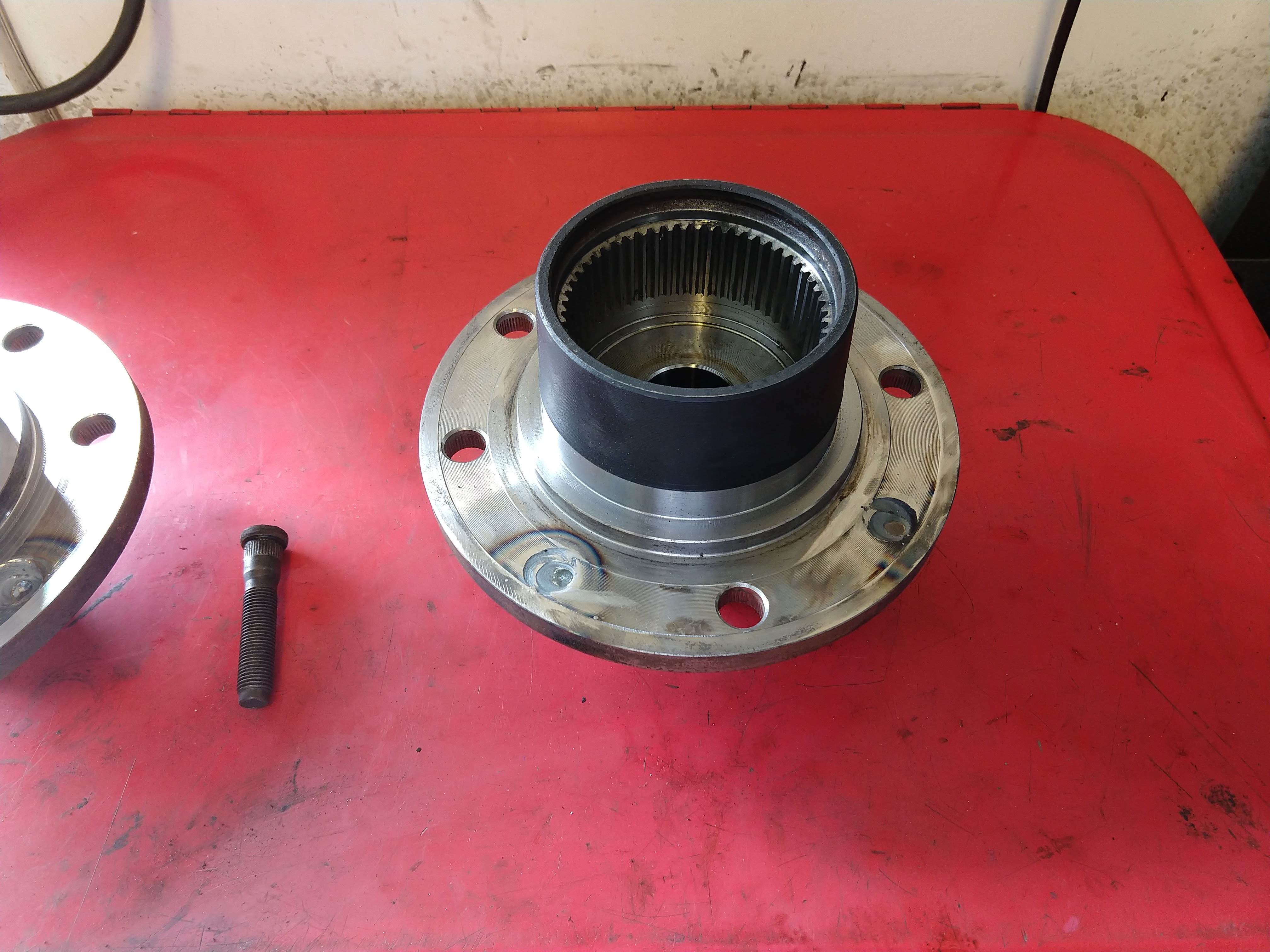
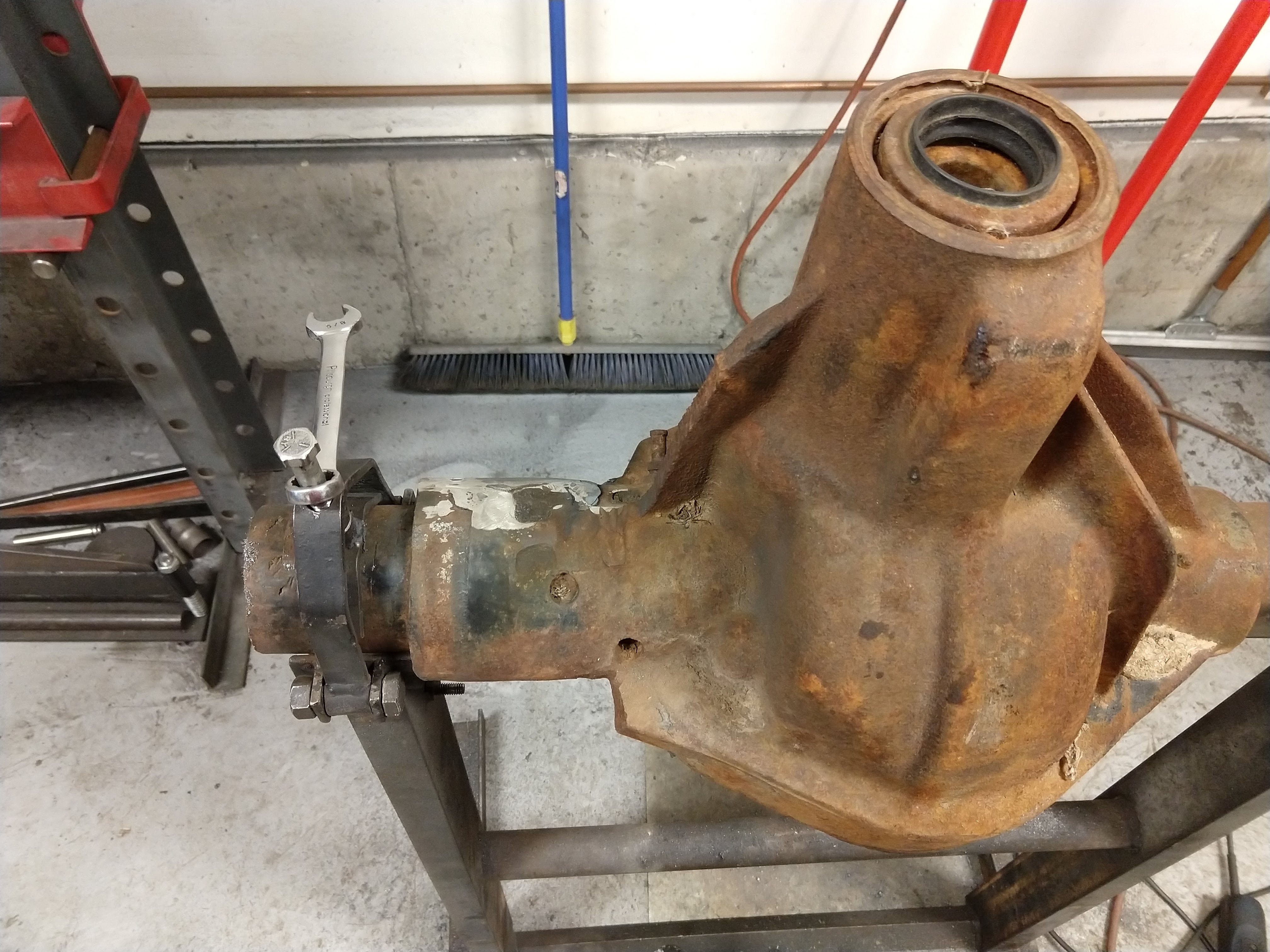
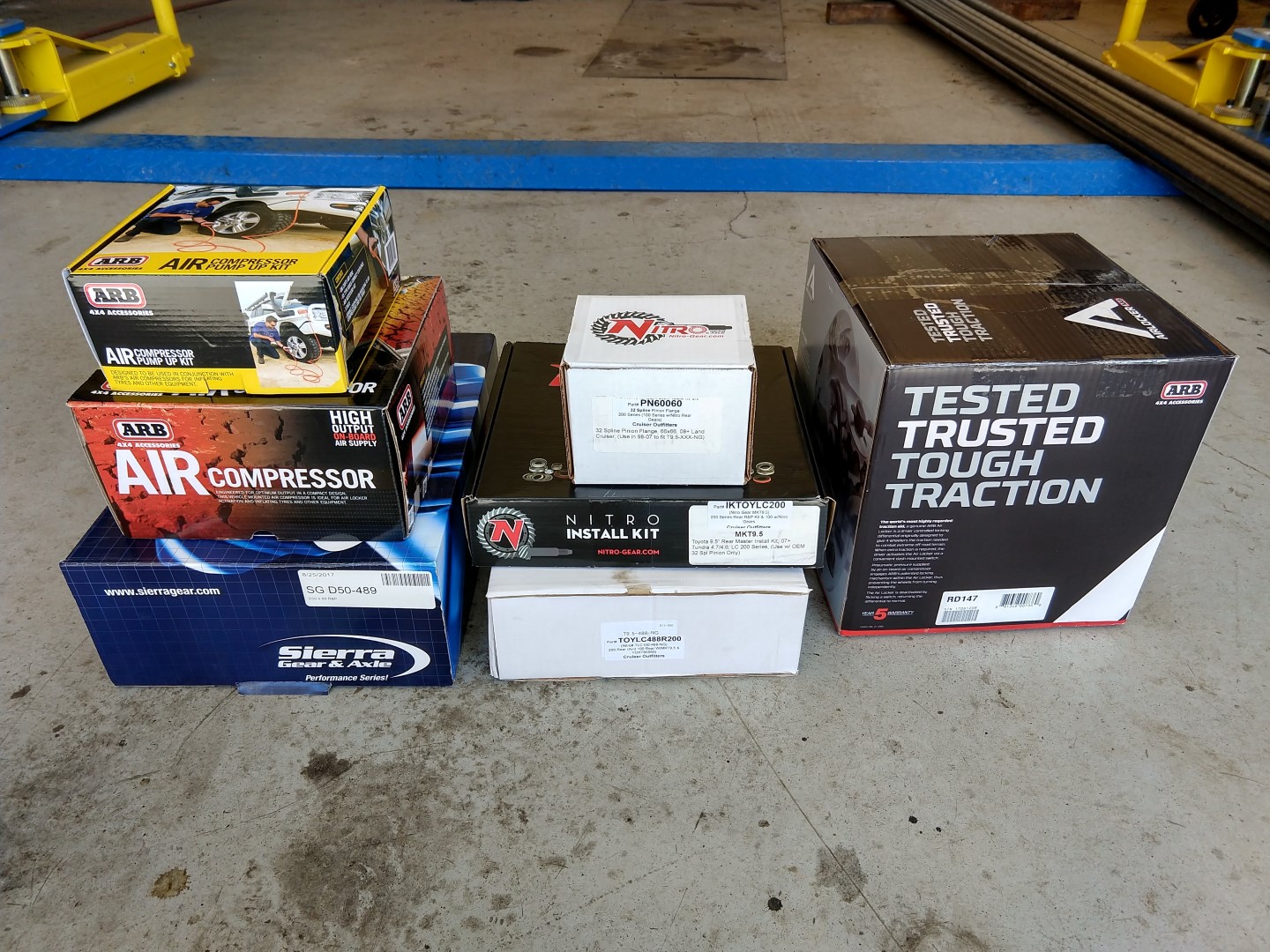
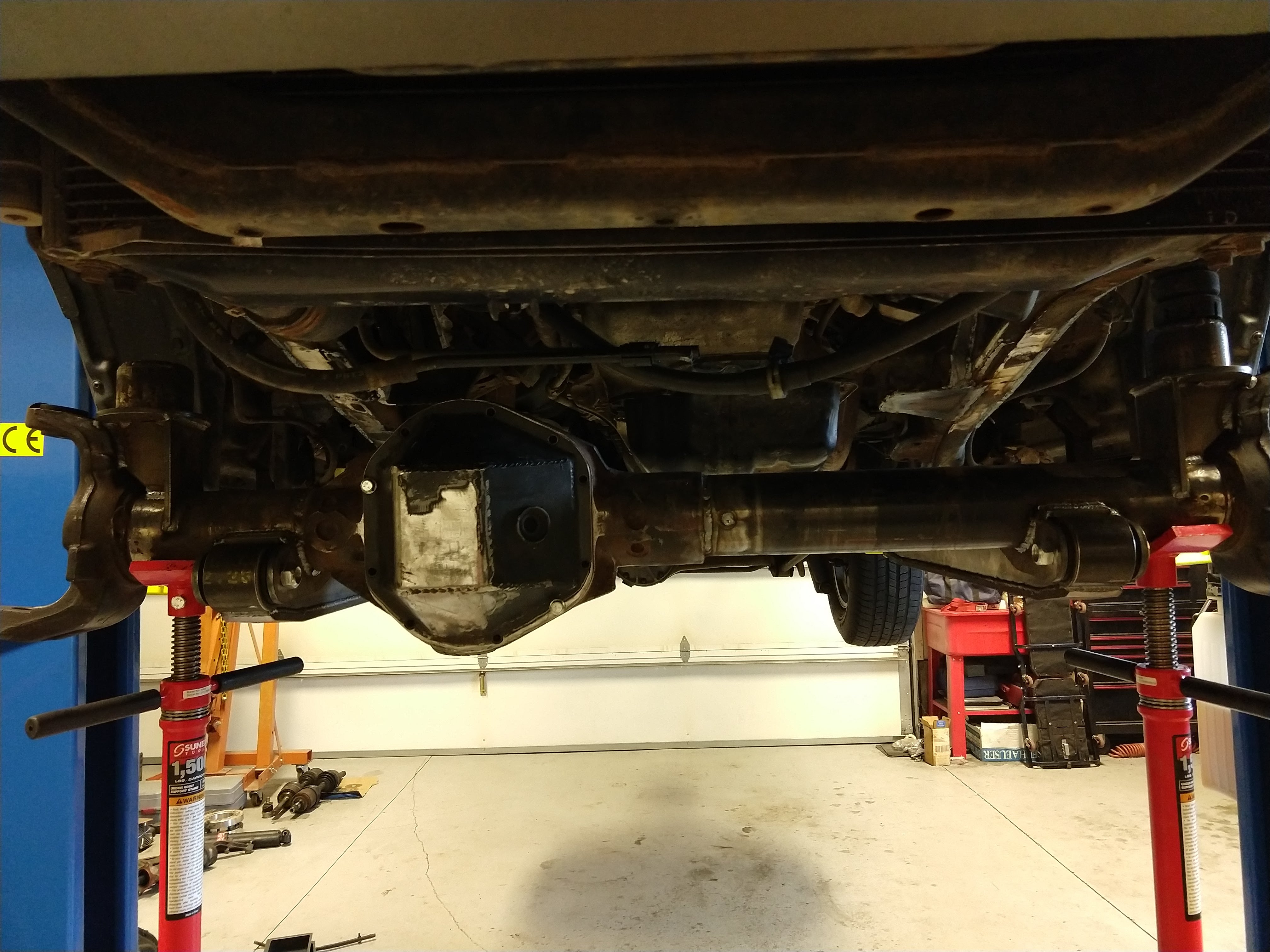
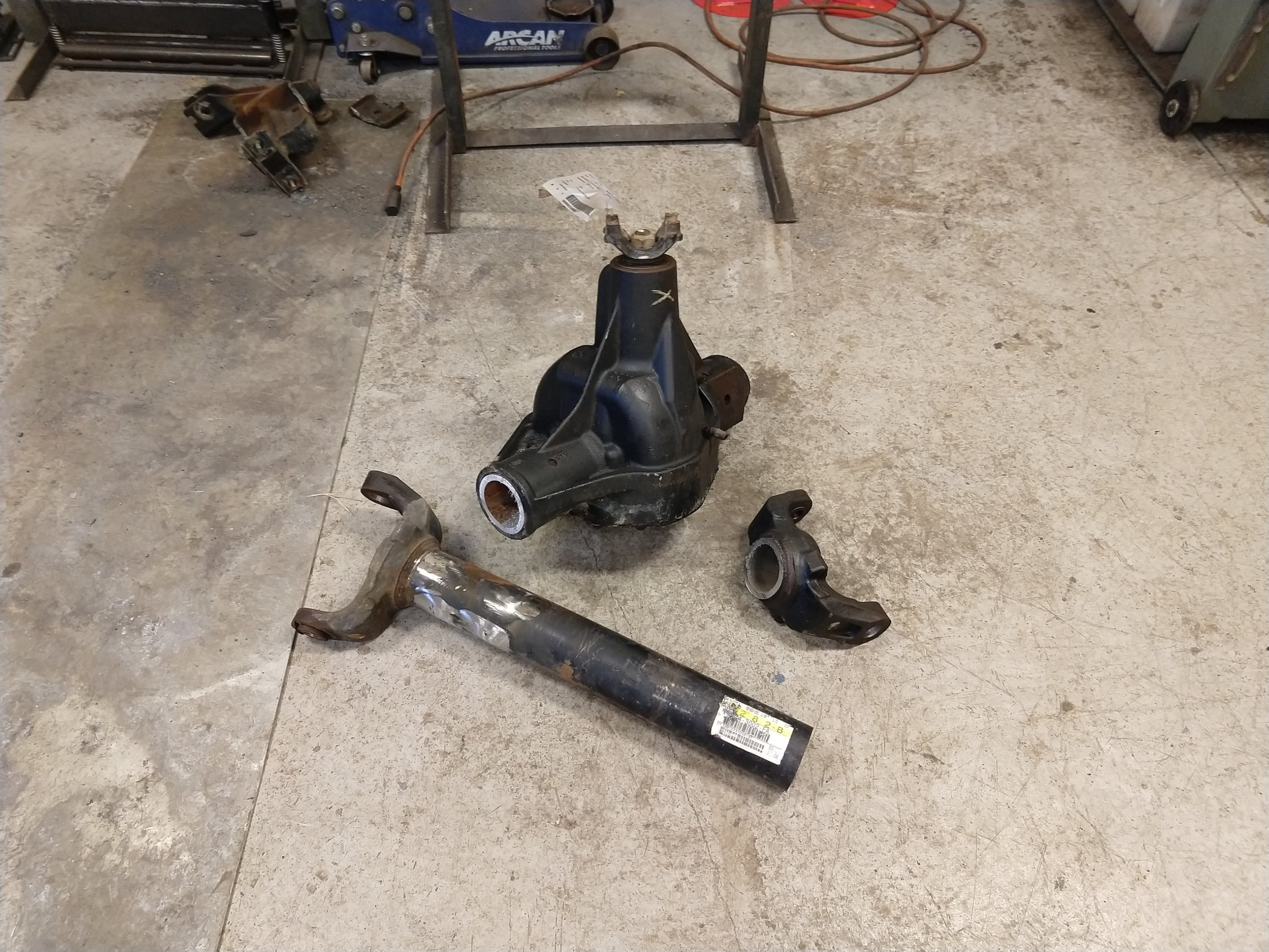
I started collecting parts a couple months before beginning any surgery on the Cruiser. I started with a couple of Super Duty Dana 60’s.
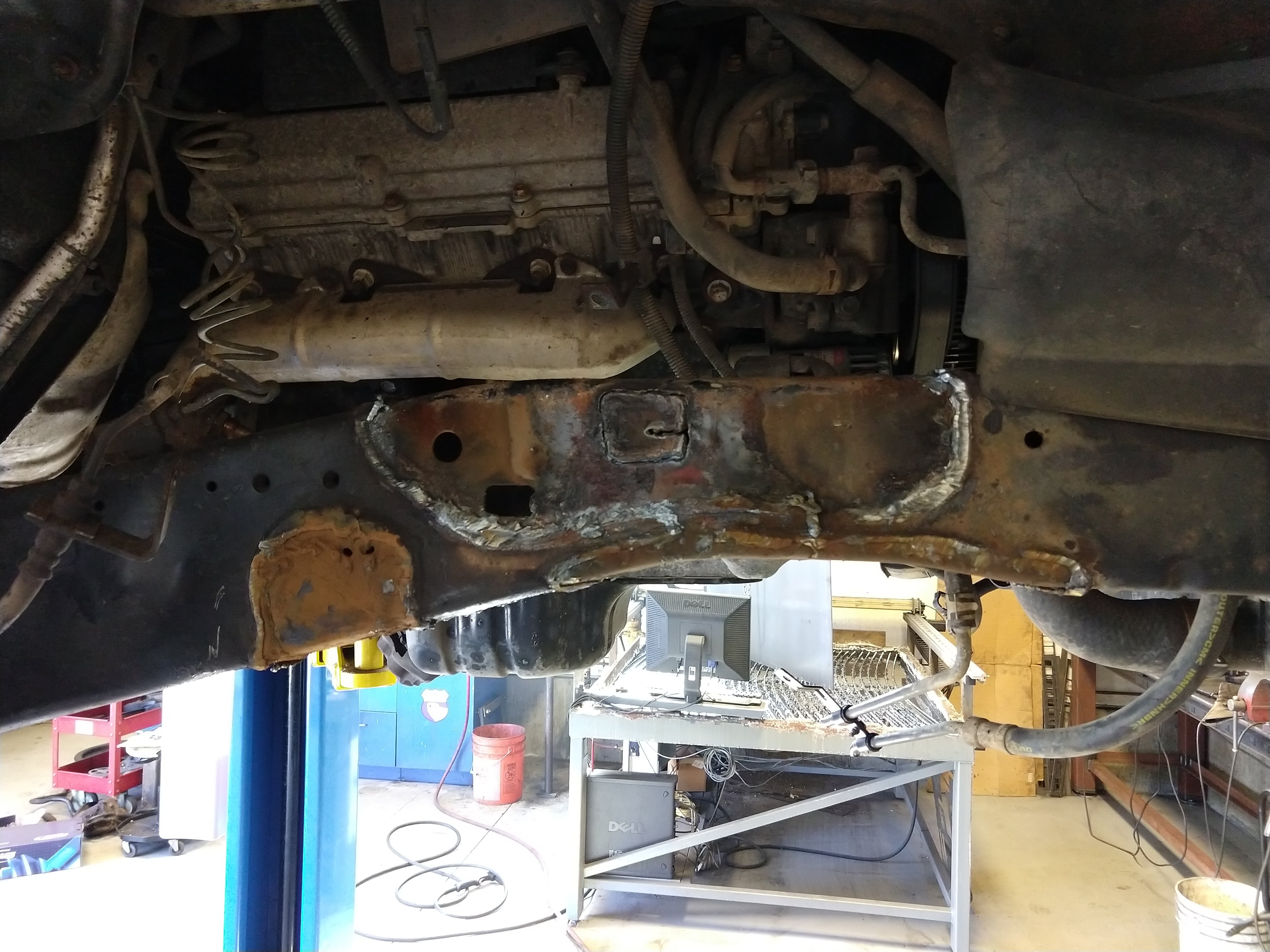
Ruined the first one.
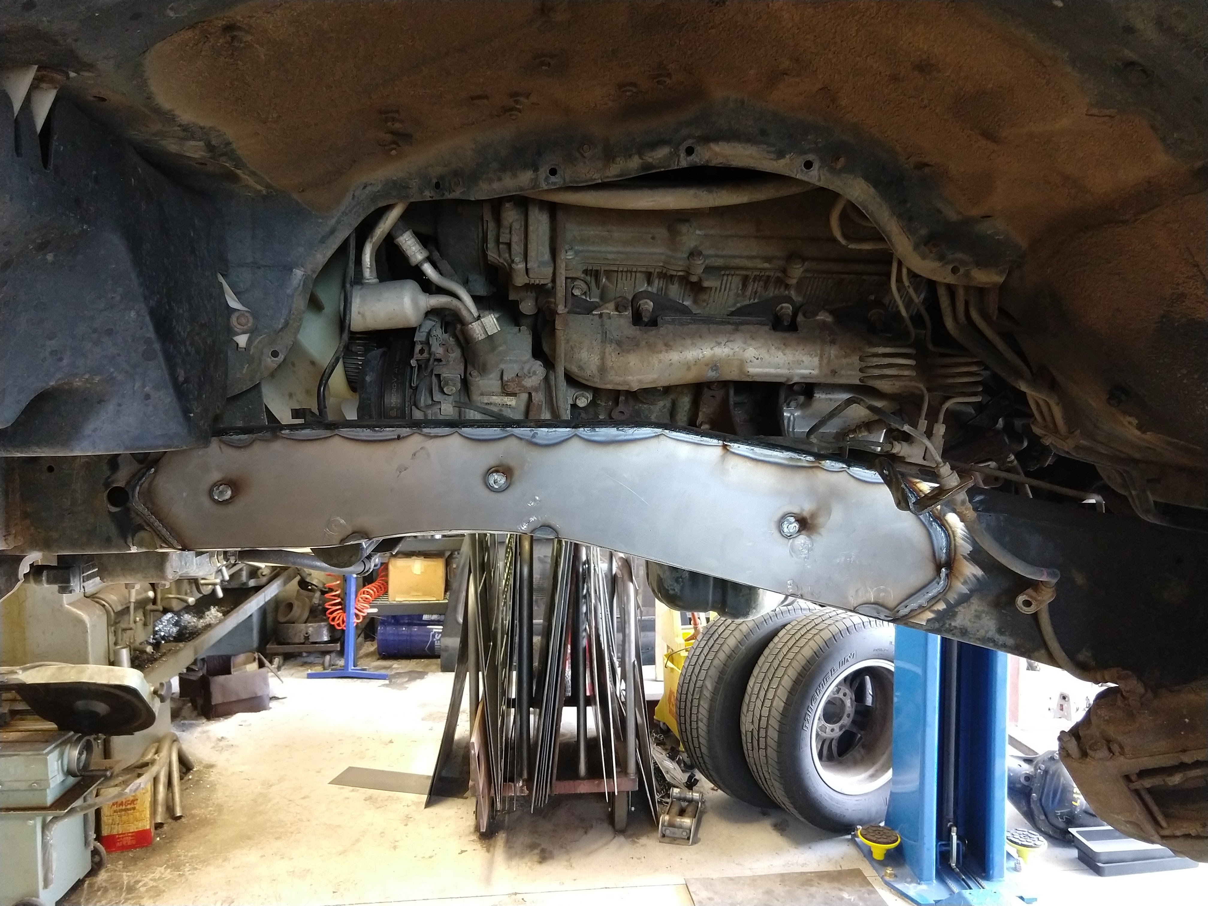
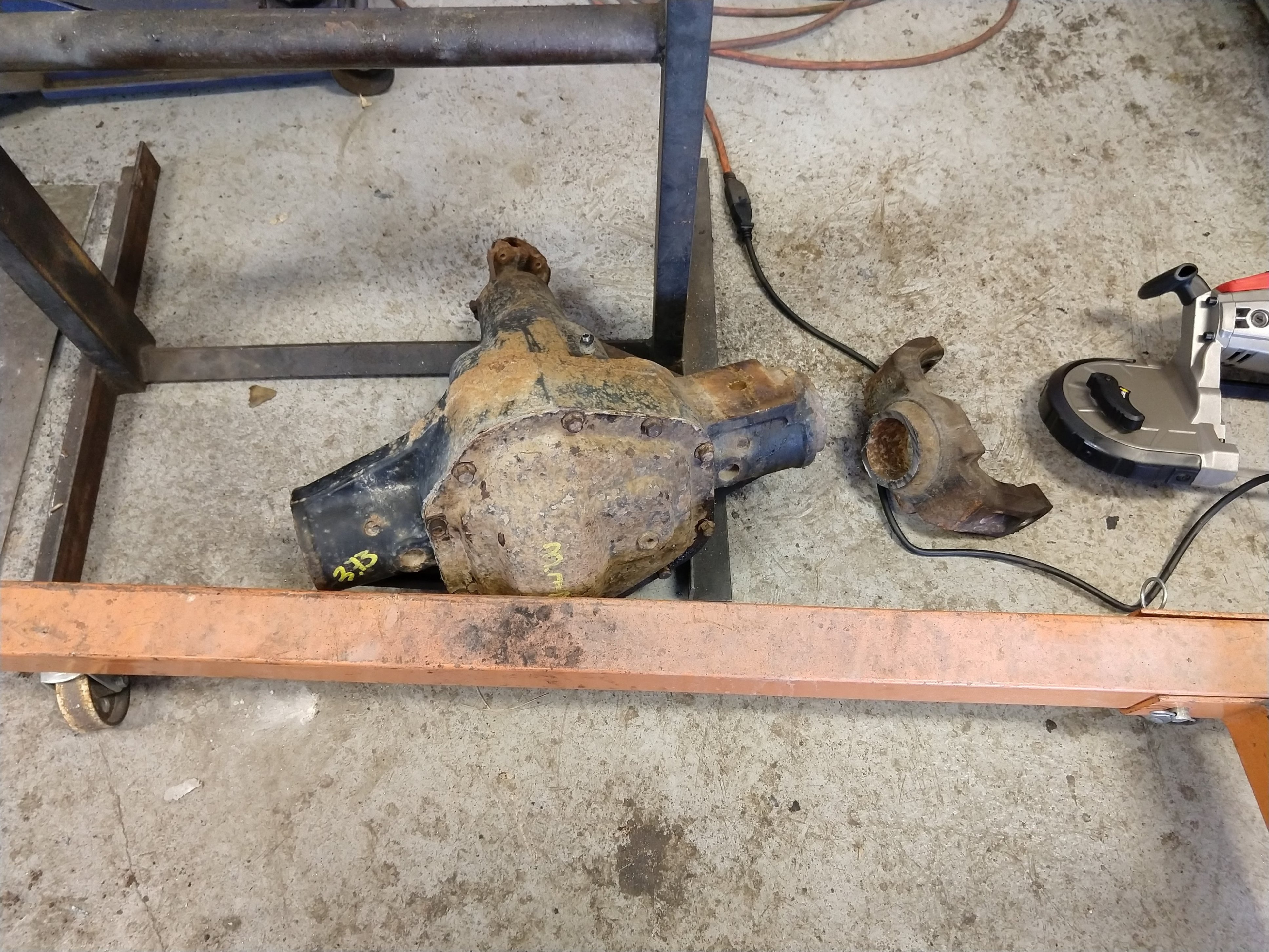
Ruined the second one.
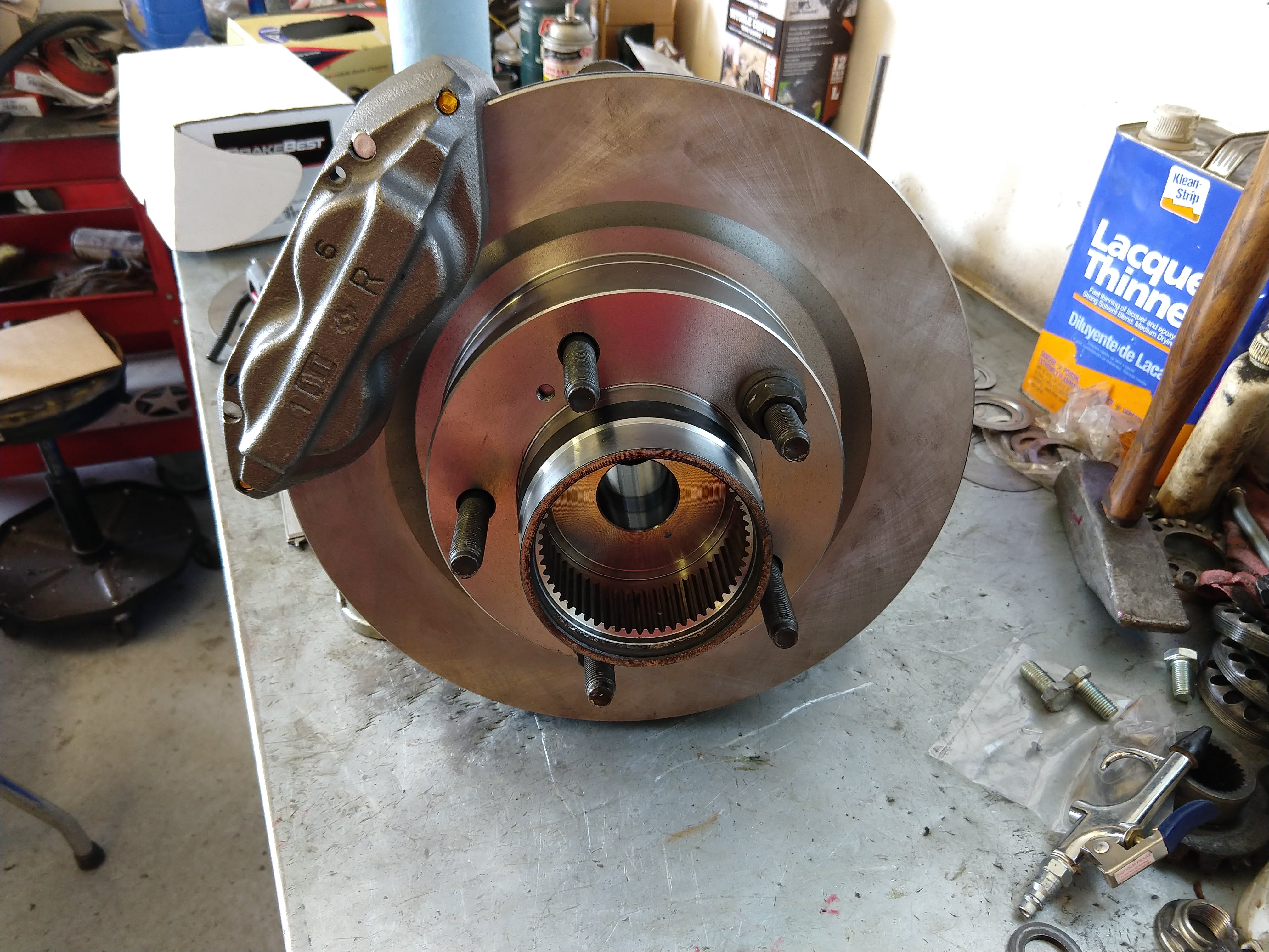
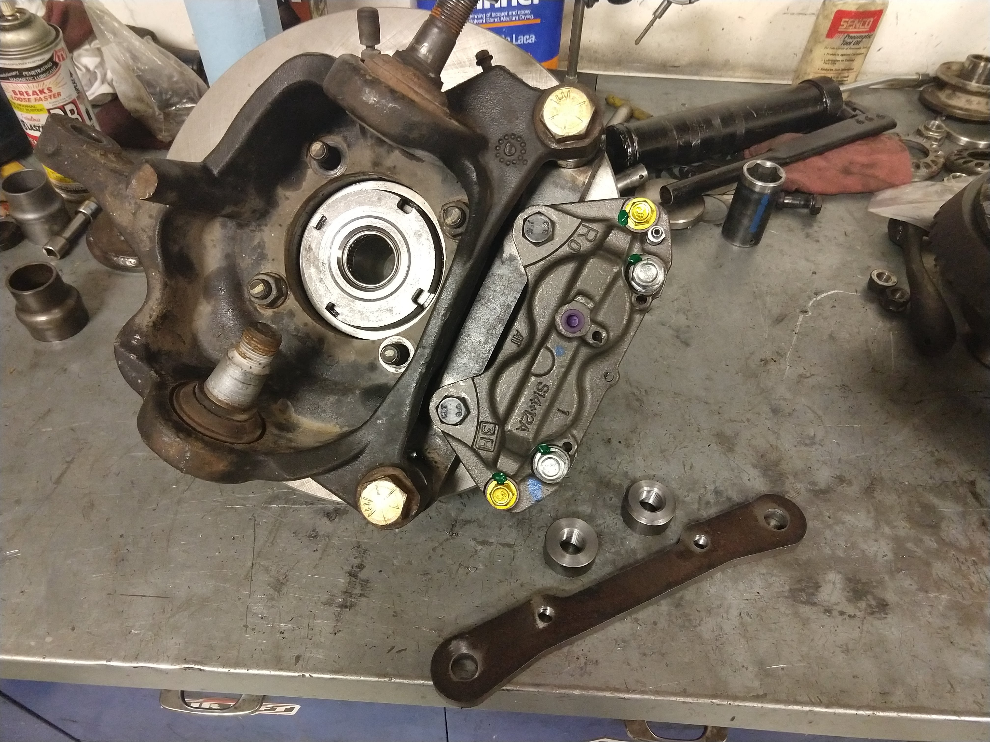
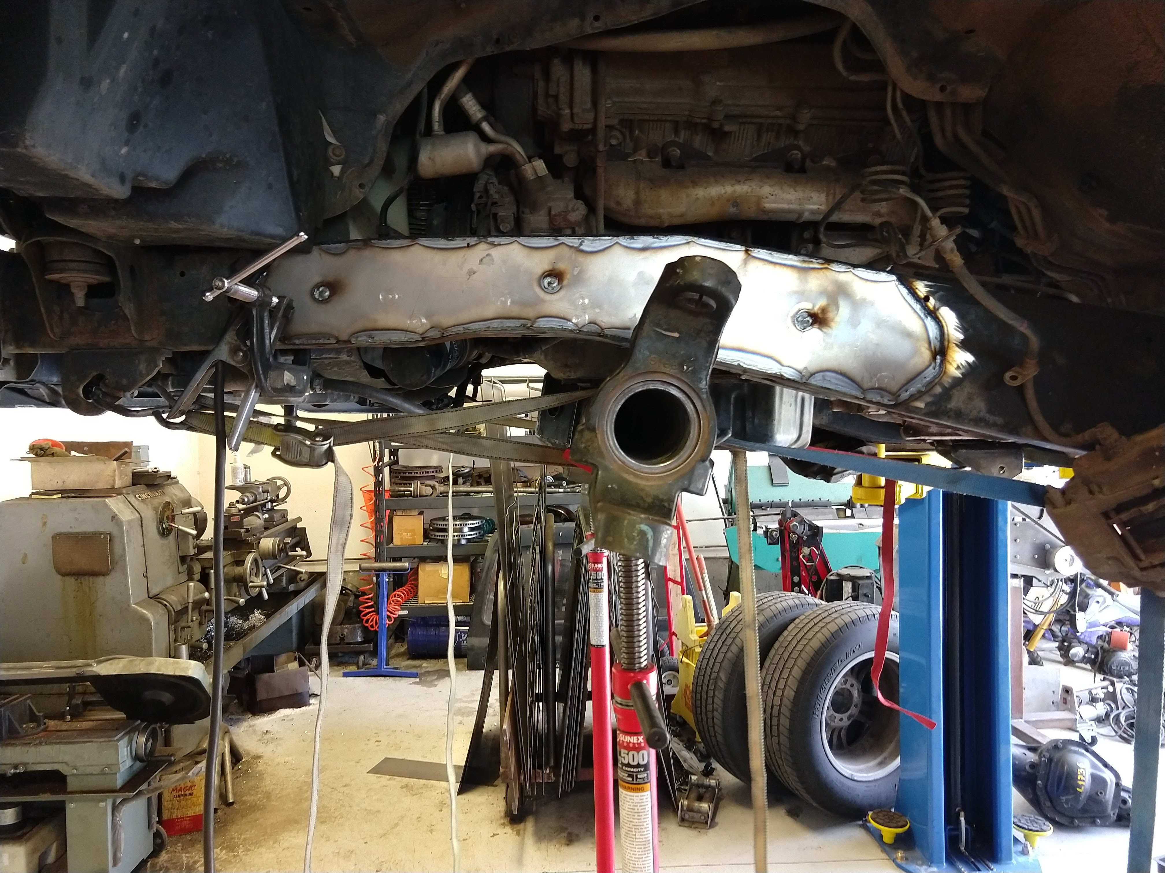
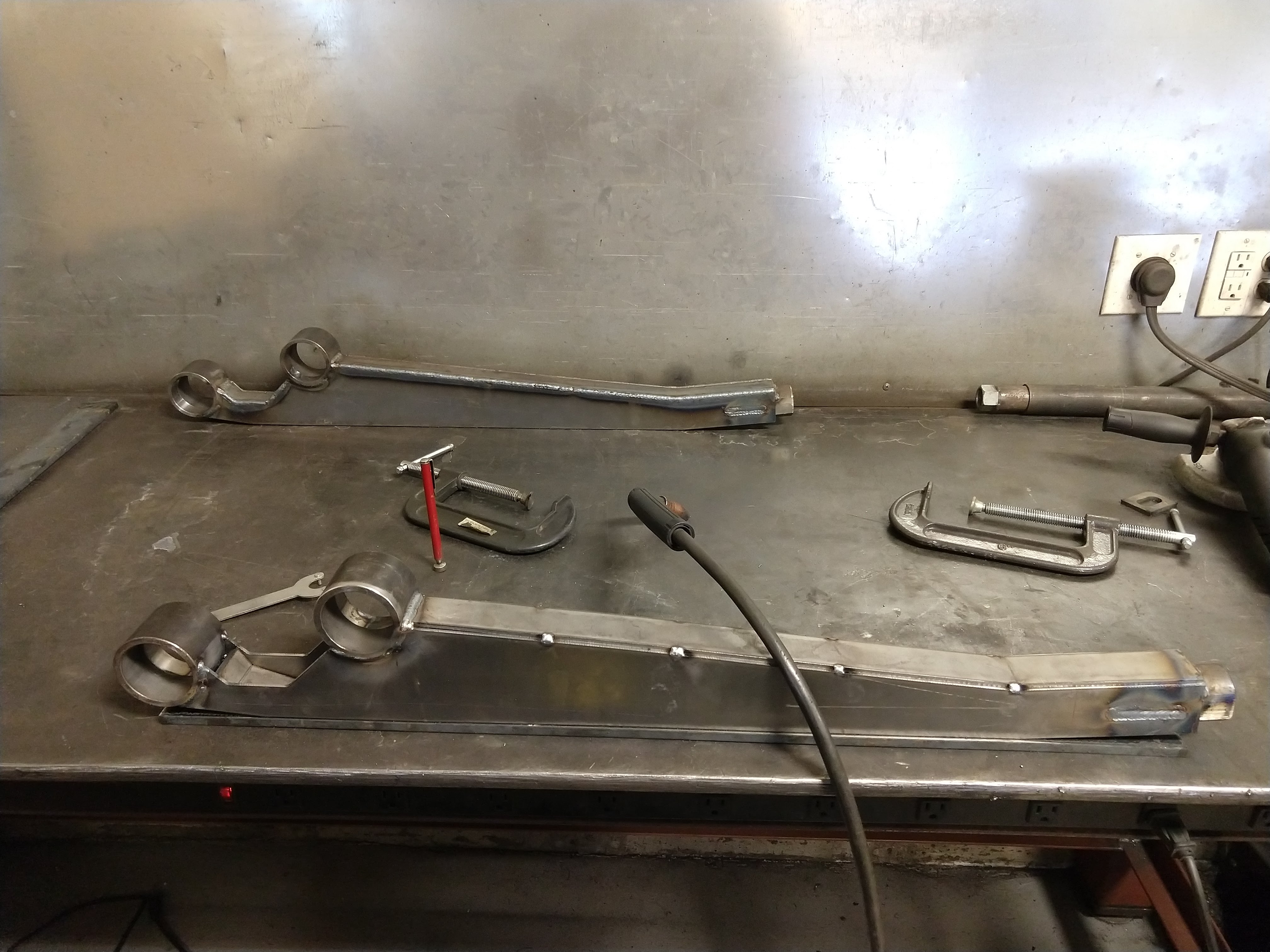
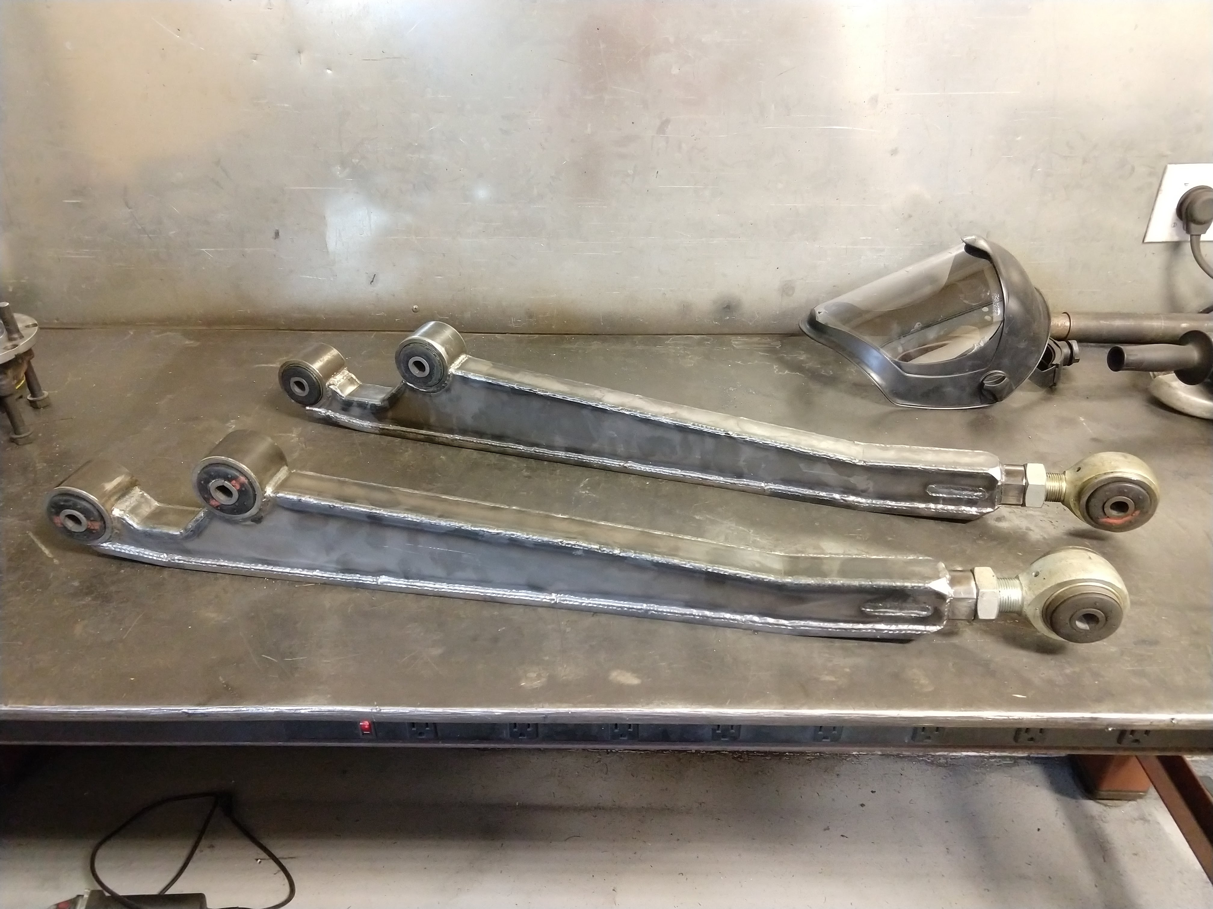
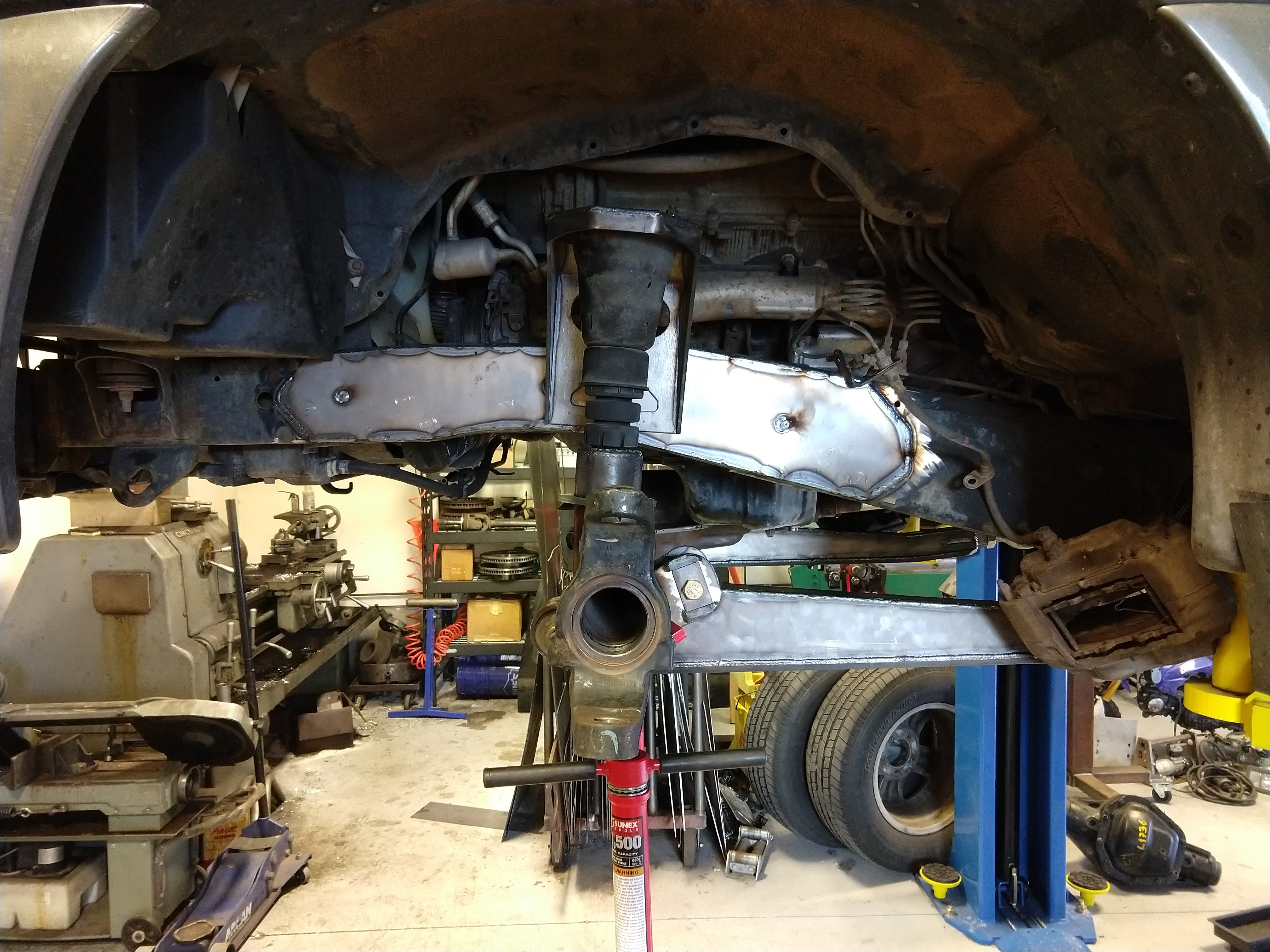
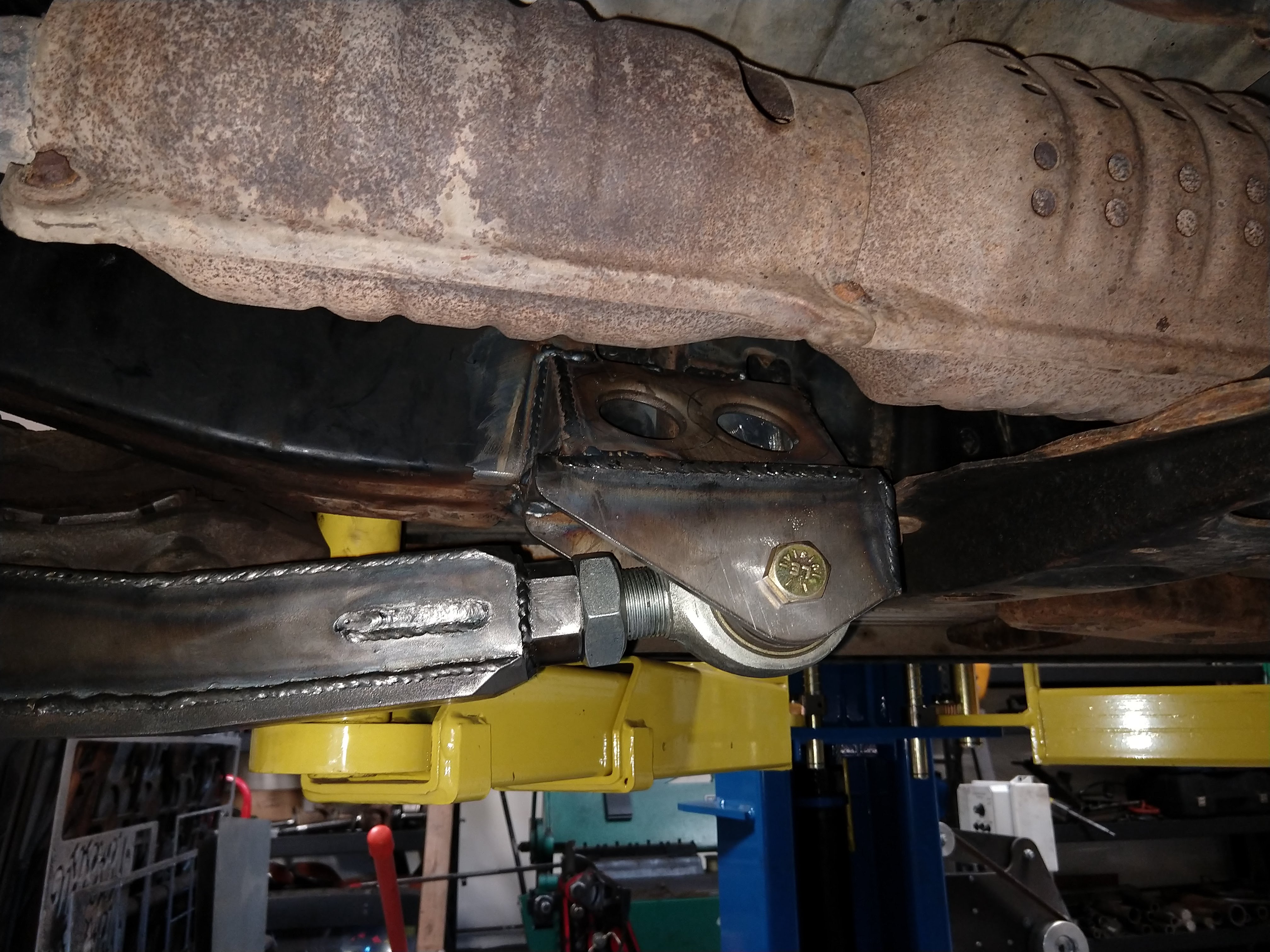
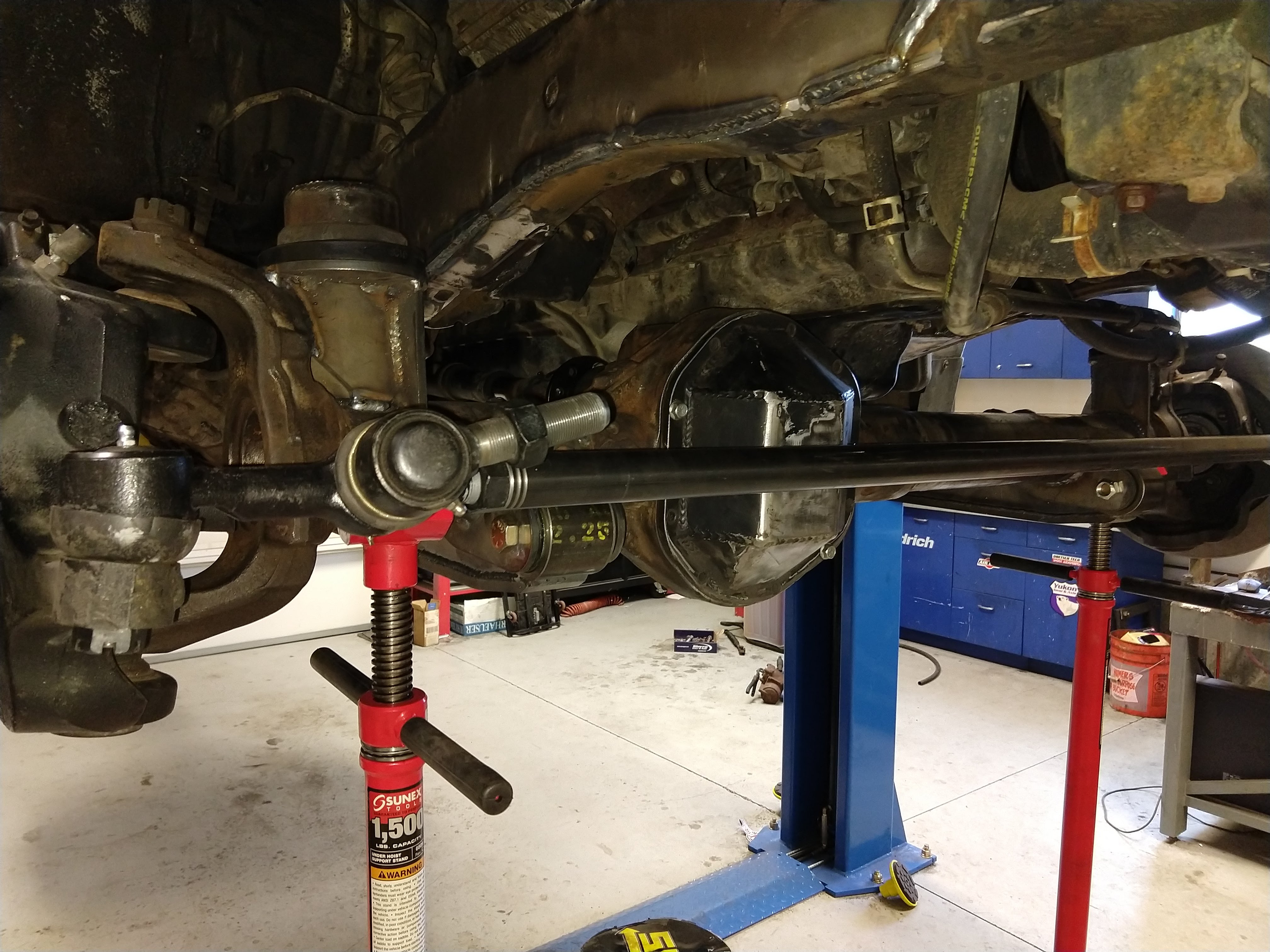
Clean brackets off both long sides. (the short side knuckles went to a friend who is building an axle)
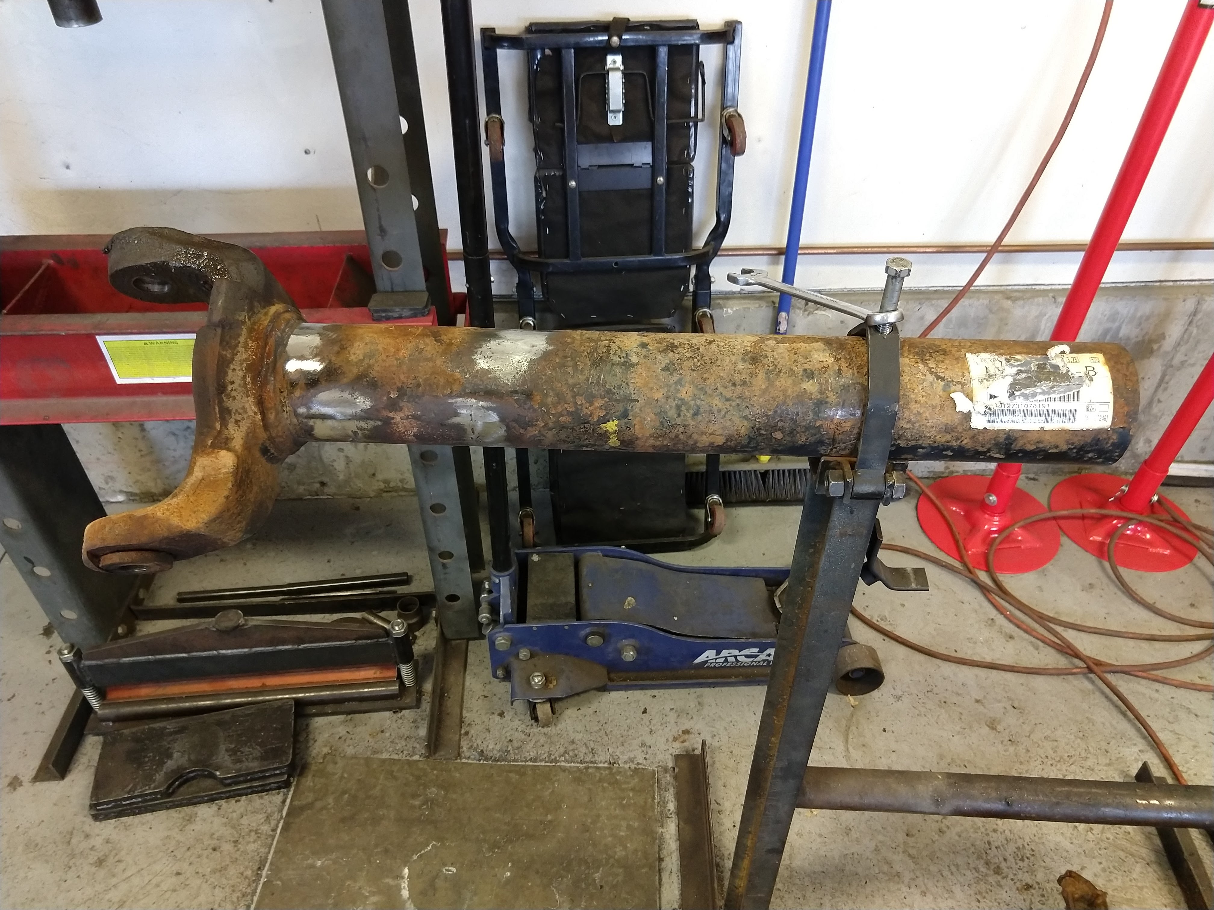
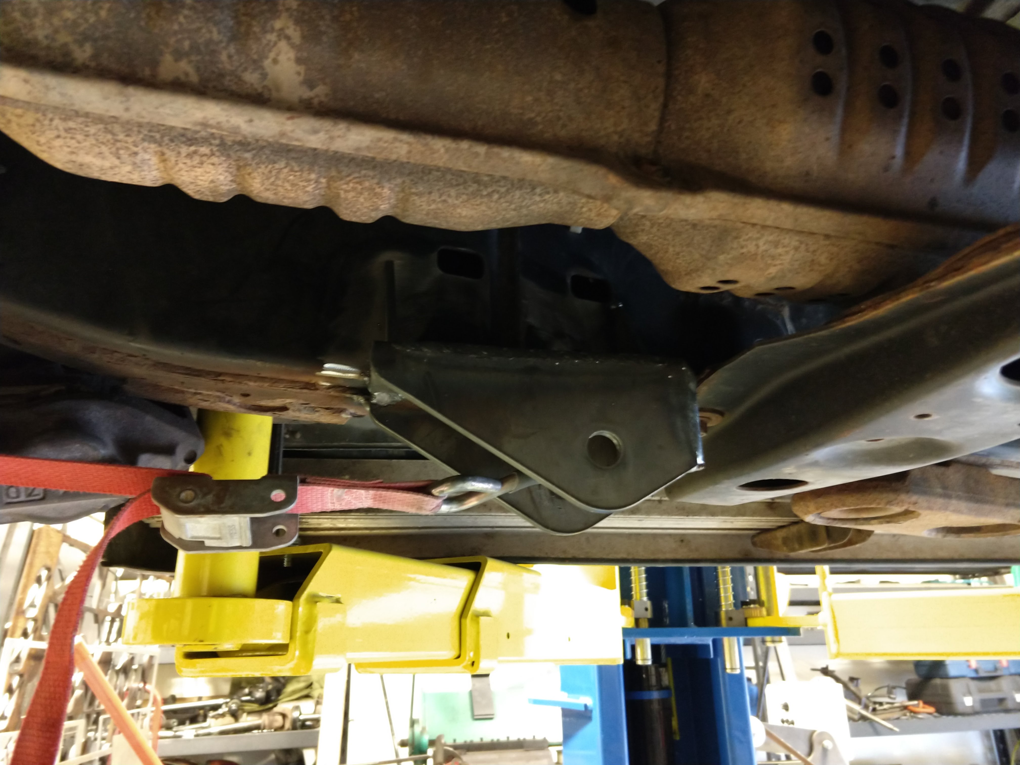
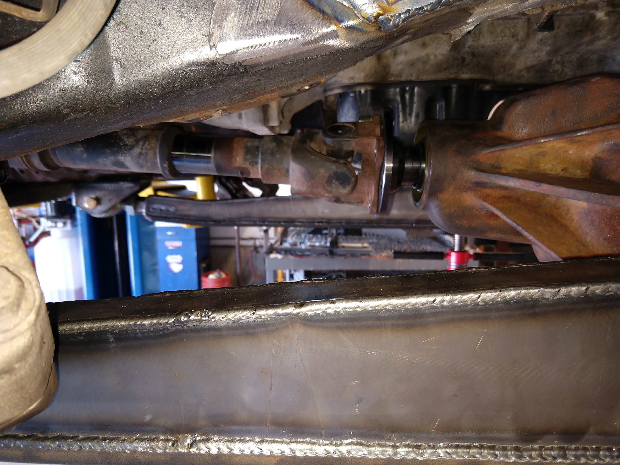
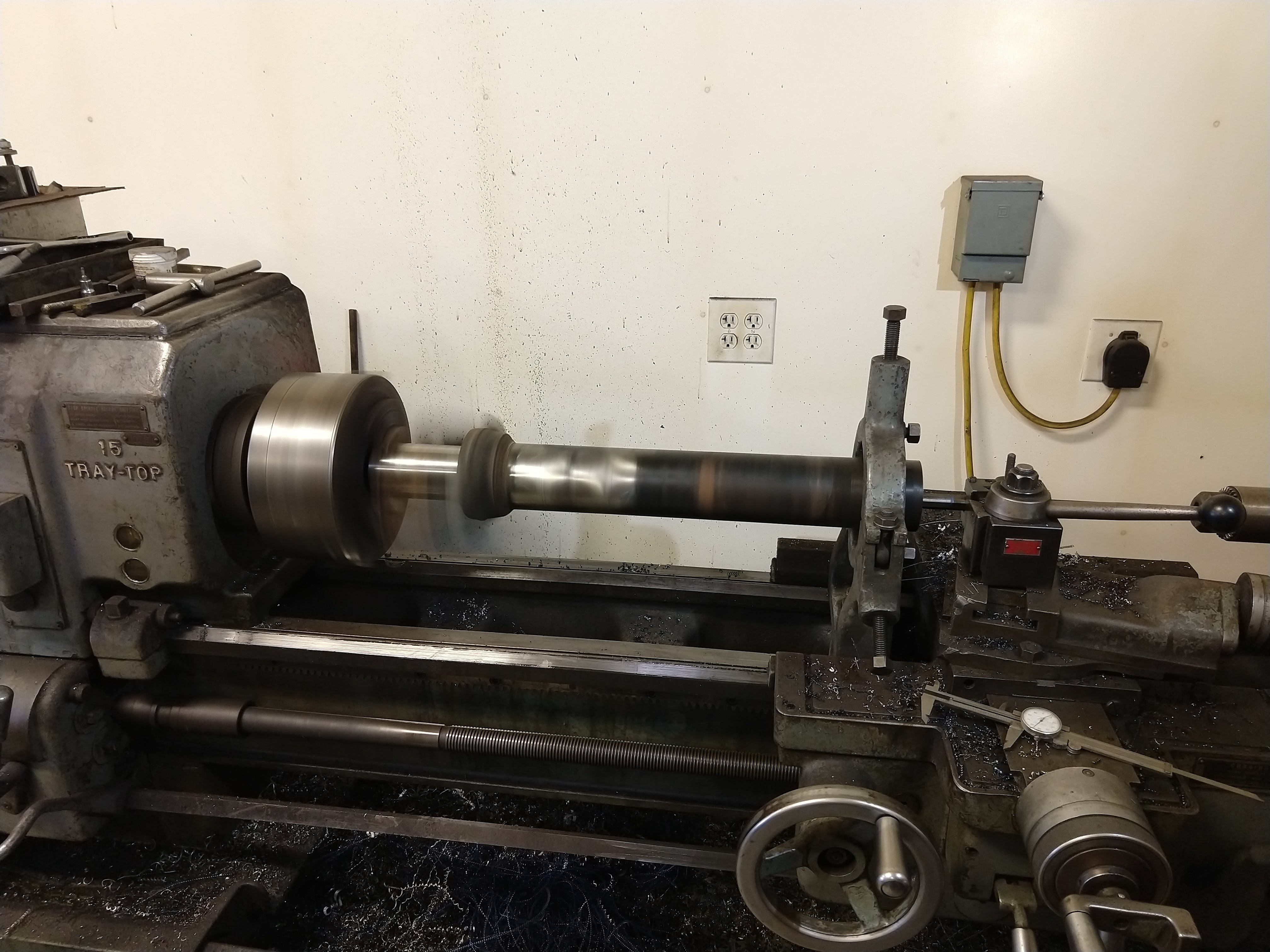
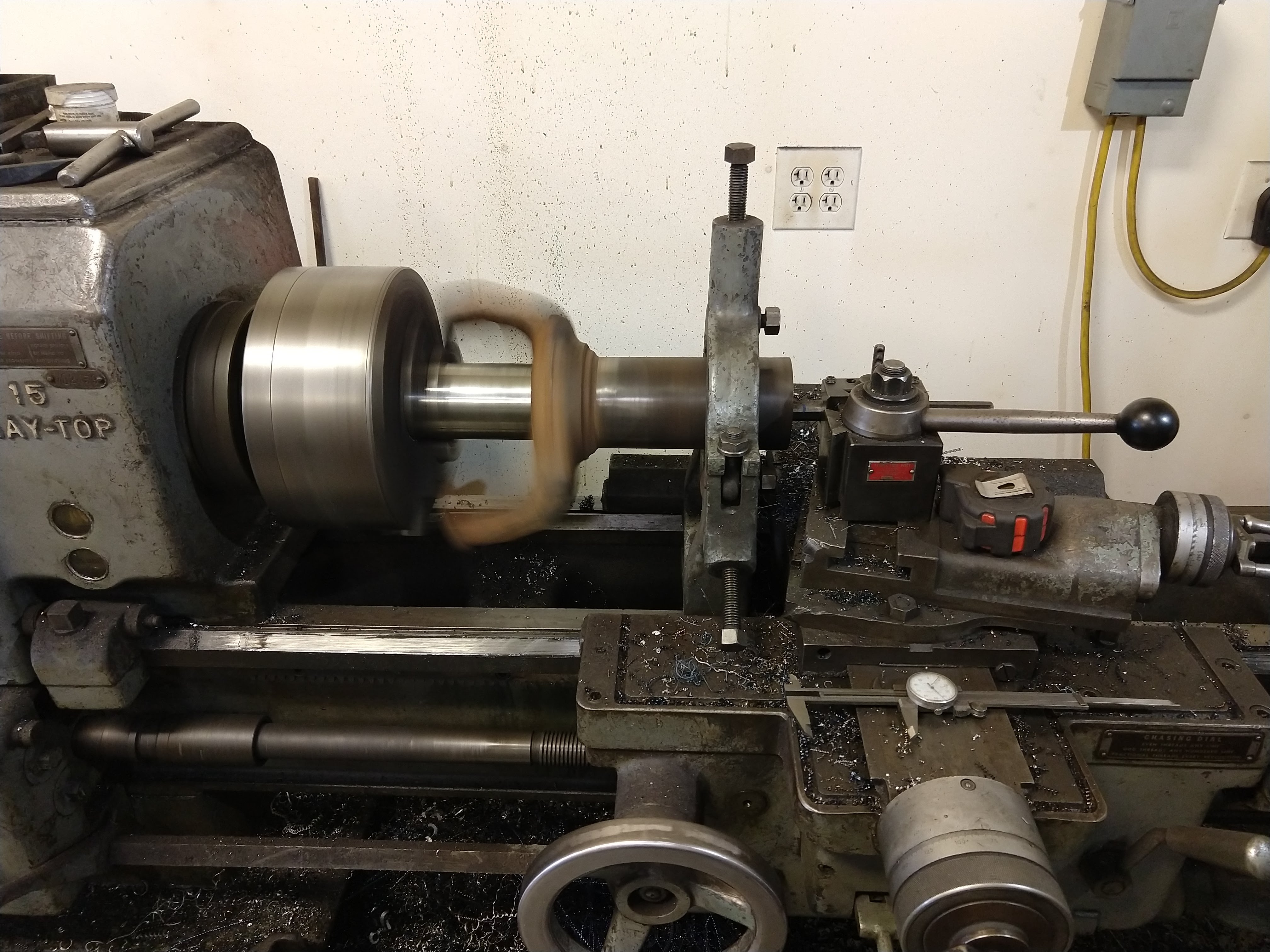
Cut to length, and bored the end out a bit on both sides.
A little back story: a couple years back we acquired a ’93 80 series Land Cruiser, and fell in love with most aspects of it. The failings of that truck are the lack of power, and associated terrible fuel mileage. So I started looking at wrecked vehicles to be a drivetrain donor to do a V8 swap. While I searched, I realized how much work that swap would be (and the type of work I do not enjoy)…but I also came across a 2002 100 series, which already comes with a V8.
It wouldn’t be as powerful as the GM V8’s I was originally looking at, but still a nice improvement over the I6.
So…I got the 100 for a good deal, I thought. The repairs (naturally) cost more than I was hoping, so my “good deal” at first wasn’t so good in the end, but still OK. I replaced the spindle, upper and lower control arms, fender, hood, headlight, bumper, valence, and had the A-pillar fixed along with the new paint and windshield. The frame was also straightened…as much as it could be.
The body shop that was doing the work couldn’t get it quite straight, and bent their frame rack trying. So…with the frame not-quite-straight, my alignment was always just a bit off. There was some negative camber on the passenger-front, the caster was near zero and the wheelbase was shorter on that side. Some of that could have been remedied with some adjustable upper arms, but overall my wife and I were just not happy with how well it drove. I can fix it!
Here’s the “before”. 30mm rear spring spacer, torsion bars cranked to match, 18” 200 series wheels.
You can spy my beloved 80 in the background here.
I started collecting parts a couple months before beginning any surgery on the Cruiser. I started with a couple of Super Duty Dana 60’s.
Ruined the first one.
Ruined the second one.
Clean brackets off both long sides. (the short side knuckles went to a friend who is building an axle)
Cut to length, and bored the end out a bit on both sides.