Not off-road related but my project for the past couple of nights.
I had to take a slight deviation from my utility trailer project. I have had so many personal projects that need to be done I haven't had any paying ones in the shop for a while. I need to hurry up and get my own stuff done so I can get back into the making money vs. spending money position.
Anyway, the weather had been holding out thus far and I have been needing to put new tires on our 2003 Monaco Dynasty motorcoach. I have NOT been happy with the POS Goodyear G670 that were on the coach one bit. They have developed an irregular wear pattern and I thought I would have an alignment done prior to installing my new Michelin's.
The alignment was within spec but to the high side of the allowable thrust angle of the drive axle. Monaco Roadmaster rear suspensions are not adjustable, as many other heavy RV chassis are either. The guy who performed my lazer alignment told me he wouldn't do anything with it as it was within the allowable range. That isn't me. Between he and I we calculated that the driver's side drive axle needed to move forward just under .125" and the tag axle slightly less than that.
On many heavy OTR trucks they use adjustable ends on their suspension links and Volvo uses an ecentric that allows for some slight adjustment. I thought about drilling the holes out and machining some ecentrics but wasn't sure if I wanted to lose any material on the chassis mounting points as well as several of them would be difficult to get a drill in due to space limitations.
Again, the gentleman who did the alignment suggested leaving it if there were no adverse handling issues. My wife and I like to travel mainly on two lane country roads when we travel and I notice that due to road crown the coach does drift off slightly when letting go of the steering wheel. On concrete interstates it is fine. I opted to move the driver's side forward .125" so it will actually help to hold to the road crown a bit.
First off, the reason for all this. Baby gets new shoes. Michelin XZA2 Energy tires in a 295/80R22.5 size. I am replacing all four drive tires, taking the two best tires from the drive axle and moving them to the tag axle and I will also be putting two new steer tires on. Good thing I am done paying for my son's college because there went a years tuition.
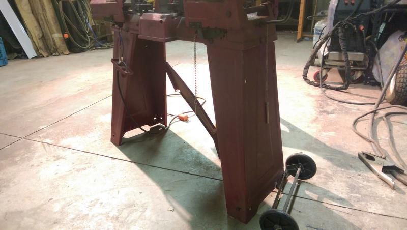
Here are the two trailing arms (control arms) that I will be removing to lengthen. Upper and lower on driver's side. Don't worry, all the weight of the coach is NOT sitting on those two jackstands under the hub. I have my 20-ton jackstands under the rear of the frame and those two 6-ton jackstands are merely holding the weight of the drive axle because I dumped the air out of the rear suspension to allow some movement of the axle.
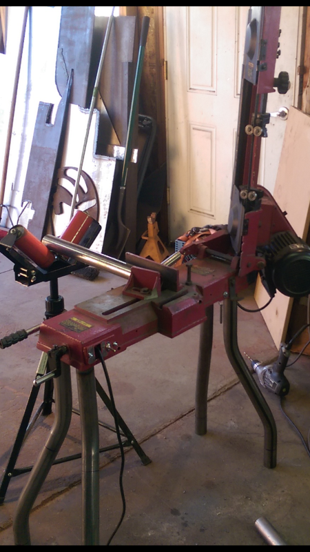
Make-shift jig setup on my welding table. I clamped some large tubing down so I could make two borders to hold the trailing arm, take some measurements, cut and then insert the trailing arm back into the jig and clamp it to the correct length.
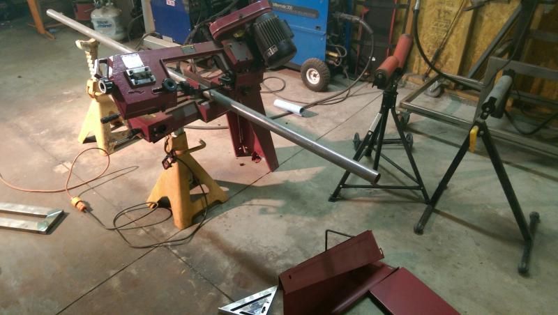
Cutting the trailing arm in my horizontal bandsaw.
I had measured the outside diameter of the square tubing of the trailing arms and had prepared for two separate methods of sleeving the trailing arm. I dug through my steel supply and found a piece of trailer hitch receiver tubing left over from one of the various trailer hitch projects. This measures 2" inside diameter and would work to sleeve the outside of the trailing arm. I was really hoping that the 2" square tubing that Roadmaster used for the trailing arms was .250" wall thickness because I also had a few small pieces of 1.5" O.D. x .250" wall square tube in my scrap bin. This would be my preferred method which would allow me to sleeve the trailing arm internally keeping the outside dimension the same as OEM. Not that sleeving it externally would be any weaker or stronger, just that I wanted to keep the trailing arm as near OEM appearance without sacrificing strength as possible.
All the planets were in alignment, the wall thickness of the trailing arm was .250" so I was able to use 1.5" square tubing to sleeve internally.
I then went one step further and put the trailing arm back into the horizontal bandsaw and removed a .125" sliver of steel. This will allow me to have just enought of a gap in the joint to allow full penetration and let the weld bite hard into the inner sleeve as well as both halves of the trailing arm for a very solid link. In addition, I knew there would be some shrinkage or pull back putting that much heat and weld into the trailing arm. I actually set the overall length @ .156" thinking it would pull back approx. 1/32" upon cooling.
I also drilled a few .500" holes in both halves of the trailing arm to allow me to rosette weld (plug weld) the inner sleeve to the trailing arm. Root weld and rosette welds completed. For some reason I don't have any pictures of the internal sleeve but there is a 6" length of 1.5" square tubing inside the trailing arm.
While I was waiting for the root weld to cool slightly I decided to grab some polish and run a coat of polish around my wheels.
When my wife and I bought the coach in 2007 the previous owner had neglected the wheels badly. I don't think they had seen a coat of polish in their first four years. Upon our purchasing the coach, I removed all the wheels and polished them with a compounding pad using tripoli and jewelers rouge bringing them back to nearly new shine. Now once or twice a year I merely have to run around them with a coat of Busch's Aluminum polish and they look amazing and bead water off nicely.
I then moved on to complete to top pass on the trailing arm.
After cooling I threw it back into the jig to test for the final measurement. Dead nuts on @ 1/8" over the starting length. It shrunk back exactly where it needed to be.
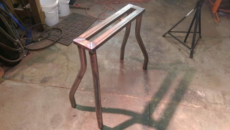
After cooling I applied a heavy coat of chassis paint, installed the lower trailing arm, removed the upper trailing arm and performed the exact same procedure. Here is the upper trailing arm completed and ready for paint.
Next I will snap a couple pictures of the completed repair/modification and then another once I get all the tires/wheels installed. I worked late last night and had to install the upper trailing arm and clean up tools in the dark so there wasn't enought light to take pictures of the completed, painted and installed trailing arms.
Over the weekend I will perform the same procedure on the tag axle trailing arms but will only move the driver's side forward .062".
Mike.