BlackSheep's Bar-B van

In June of 2023 while driving down Montezuma Canyon road in my Ford Transit 'Galahad', I encountered a creek crossing. That creek crossing resulted in the purchase of my new Bar-B van. I've named her "Bar-B the Barbarivan".

Owners Name & City - BlackSheep. My residence is in South Carolina, but I'm a hippie now mostly traveling full time in my van

Make, Model & Year of Vehicle- 2004 Ford E-350 XL Super Duty with a Quigley 4x4 conversion which was completed when the van was new.

Engine- Ford V-10

Transmission- 4R100

T-Case- Borg-Warner manual shift 1356, 2.69:1 Low range

Axles- Dana 60 Semi Float rear, Dana 60 front. 3.73 gearing

Suspension- Coil spring front, leaf spring rear. Bilstein shocks

Wheels and Tires- 265/75R16 BFG All-Terrain KO2 on stock 7x16" steel wheels and full moon hubcaps :rofl:

Winch- I have a 10,000# winch on a receiver carrier that I need to wire up. Not really the right capacity for this rig but it came with my F250 when I bought it.

Favorite Trails- to be determined. This van is much more capable then the Transit so I will (and have) take(n) it on trails that I wouldn't have driven the Transit. It's a campervan so there will be limits.

Other-
I purchased this van on June 21, 2023 from the 2nd owner. The van had 47,xxx miles on it. The 1st owner had the Quigley 4x4 system installed as well as a Fiberine 20" Aerodynamic high top. Then that 1st owner did a camper conversion to suit his needs. That 1st owner was from Patagonia and stored the van in Southern California in between making photography trips to the USA for which he used the van.

The 2nd owner purchased the van in 2020 in the height of the world madness. She and her husband, living in Tuscon, Az, installed a roof-top AC system and the shore power connections to run it. They also did a few minor upgrades to the camper electrical system to allow for charging the LiFePo4 100AH battery off of AC power. They made no changes to the interior designed by the original owner.

Here are some photos of the van after I purchased it and brought it to a friend's house before bringing it back to SC:


Note the extremely out of place look of the RV AC unit on top of this otherwise awesome looking van!
IMG_4068.JPG


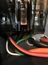
That's a 5 gallon gas tank hanging off the back. You can also see the Maxxair Deluxe fan on the roof. You'll also see the 30A electric so they could run the AC system.
IMG_4118.JPG


Looking towards the back of the van. The AC control unit hung down a few inches. At 5'5" I could still stand under it but it was a little tight. The platforms covered in carpet can be used as a suspended bed platform. They were a major pain to put in place and I knew they would be removed. I also knew the AC would be removed.
IMG_4102.JPG


Looking towards the front - that cavity is above the cab of the van. It is a great storage place with lots of room.
IMG_4103.JPG

Not sure which previous owner installed the swivel on the passenger seat - a very nice feature. on the left you can see the opened bench which has a lot of space for storage.
IMG_4107.JPG


The cabinets on the passenger side. Note that this van has a slider door rather than the barn doors. I wanted the barn doors but with all the other cool stuff about this van, I decided I could live with the slider door. A reasonable sized Dometic chest style electric cooler sits on drawer sliders with the camper electronics housed in the space below the fridge. The cabinets are a unique design using 1/2" square tubing framework with nice wood (type I don't know but not Pine) inserts. I liked this style as it is pretty unique for all the van builds I've seen.
IMG_4111.JPG


The driver side cabinets are of similar style. The bench / storage was about 74" long from behind the driver seat abutting the rear cabinet.
IMG_4112.JPG


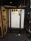
The 17 gallon water tank is on a platform with the pump and some plumbing under the platform. The pump switch is at the slider door, with the electronics. The only outlet for the pump is the hose you see in the photo.
IMG_4113.JPG


Some close-ups of the rear cabinets. I knew I would be modifying the frames for these cabinets. These pictures are for reference.
IMG_4114.JPG

IMG_4115.JPG


Plans: Modify the interior to suit my needs. Those needs are:
--> fit my bicycle inside the van
--> plumb a sink and an outlet for a shower. This will require also a method to capture grey water and a countertop to mount the sink.
--> build space to have my larger Dometic fridge so I can use the existing as a freezer
--> Build in a real bed platform. I must be able to sit up on the bed. Consider orientation of the bed (N-S or E-W??)
--> Build in a space for my 2 burner propane stove. Plumb the propane so I can attach to my Joolca propane fired shower system. Have a space to store the propane tank
--> Consider options for carrying the Joolca, max-trax traction boards, vehicle fluids, oil change kit, etc. outside the van.
--> Figure out how to cover the hole once I remove the roof-top AC unit.

I may add more bullet items as I add more posts documenting the actual build since I've already done that work. These are the big ones though.
 
Last edited:

BlackSheep

baaaaaaaaaad to the bone
Supporting Member
Yesterday I started on fabbing the electrical box extension that will fill the space beneath the freezer when it is in it's drawer closed position. Today I got the frame tacked together:
IMG_5218.jpg

Then I mocked it in position to check the fit
IMG_5219.jpg
IMG_5220.jpg

I made a couple of minor mistakes. They won't really have a negative impact but my intention was to make the frame extension bolt down to the floor with 2 more bolts just as I've bolted in the main section. Well, if you look closely you can tell that I actually didn't make the extension quite deep enough. Look where the lower frame of the extension meets up with the main frame - you can see I was off by not quite 1/4". It's not a major deal I just won't put any additional bolts for the frame extension.

With it mocked up it was time to remove the cabinet and the electrical box and tack the extension to the main frame. As I was working I was thinking about how I was going to mount up all of the electronics (original box used a piece of 1/2" plywood) and how would that plywood mount to the frame. I'd examined the original pieces and with the frame being made of 1/2" angle iron it put the screws just at the edge of the plywood. So, I set up a little assembly line and made some mounting tabs. Thankfully the shop I'm in has a drill press! After marking, drilling and cutting:
IMG_5221.jpg

Then it was welding them up to the frame:
IMG_5222.jpg
IMG_5225.jpg

To fit the inverter, the original builder stacked two pieces of 1/2" plywood. The inverter will be mounted in the extension so I used a piece of 3/4" plywood that I had laying around. I cut it to shape and mounted it up. For the main section I actually removed the top layer of the two layer 1/2" plywood (not needed since the inverter was the reason behind the 2nd layer).

With that done, I reassembled and mounted the electrical box in the van. Then I started mocking up how the electronics will fit inside. I need to order a fuse block but I sure did make a whole lot more room to put that stuff!
IMG_5227.jpg

Outside the box you can see the DC-DC charger, solar charger and the AC-DC charger. There is one other component that is not in the image. All of these will be mounted in the cabinet above the electrical box. I hope to make connectors for all of the wiring except a couple of AC plugs from the AC-DC charger and the Blue Smart Charger. Those two devices plug into the outlet that you can see inside the box.

I'm sure I'm going to be rearranging some of that stuff a number of times before I actually screw it all down.

I'll need to make a new faceplate as the opening I made for the extension is actually bigger than the opening for the main box. This is somehow a result of the positioning of the drawer sliders. Maybe I could have pulled them together a little but I did not. It's ok as the original faceplate has extra holes that I won't use anyway.


Thanks for following along.
 

BlackSheep

baaaaaaaaaad to the bone
Supporting Member
I had to order a DC fuse block and a couple of AC power distribution blocks so while I am waiting I decided to work on some shelving that I had planned. In August last year I added the copper tubing to act as retainers for the baskets that sat on an existing shelf created when the OE roof was cut and the high top installed. I couldn't find any photos so this is a screen shot from my brief van tour video:
copper tube shelving.JPG

Hard to tell perhaps but the shelf isn't as wide as the baskets and depending on how I loaded the baskets, they could sag and start to fall through the gap. So, I had some wood from the original build that was about 74" long. I knew this would make a good shelf and I could cut it to the appropriate width. So, that's what I spent the last couple of days on. I got two 74" pieces which worked well for both sides from the forward part of the van to over the bed. Driver side:
IMG_5237.jpg

Passenger side:
IMG_5238.jpg

That left a gap towards the back of the van so I scrounged for other pieces of wood from the original build and found a couple of pieces about 15" long but wide enough to cut to size. Those two pieces went towards the rear.
Driver side:
IMG_5240.jpg

Passenger side:
IMG_5239.jpg

You can see they didn't go all the way to the back wall so I used another piece cut to size then I used scraps to make the edging. This gave me a shelf across the back wall. I'll attach it to the copper tubing. This will actually give me a lot more storage. I need to buy some more baskets I guess.
IMG_5241.jpg

If you look close you can see the handlebar of my bicycle in that last photo. Before I built the shelf I had to use some other scrap wood to confirm I'd be able to get the bike in and out without the shelf getting in the way. It clears!

It's also obvious that the two copper tubes are not mounted at the same level, making the shelf down a little on the left side of the image (passenger side). I'll think about whether I need to address that and how once I go to mount it up.

I need to pull all the shelving out, sand and stain it before I screw it down. If I get the sanding and staining done Saturday I'll have them all fully mounted up by Monday.

It looks like all of my electrical parts came in today so I'll be back on electrical once the shelving is mounted.

Thanks for following along.
 

BlackSheep

baaaaaaaaaad to the bone
Supporting Member
Turns out that not all of my electrical parts came in today but no worries, there’s plenty to do. After sanding and staining, then setting aside to dry, the shelving I decided to figure out how I was going to mount the water tank and pump.

I need to do better at taking before photos. The previous builder made giant holes in the floor and welded bolts to the frame. You tightened those bolts up from underneath the van. It was a pain. The first thing I did was cut those bolts off so I could work with the frame and tank/pump assembly.

I set it in place and put the rear cabinet in place so I could see where I could fit tabs to bolt the thing down. I’m using rivnits.

As I looked under the van I saw an unused seat belt bolt that looked to be in just about the right spot. Sure enough I poked a sharp dental tool up through the flooring and it was positioned perfectly. That was the first tab.

The second tab was diagonally across the frame and was easily located using the original holes and a measurement.

160D51A5-A85A-4E13-9003-9DB9A985651D.jpeg

Lower right is a 5/16 bolt with spacers underneath and upper left is the seat belt bolt also with a spacer to keep the frame level.

A source of frustration for me was to remove the frame I had to disconnect the strap that holds the tank in place. Managing the tank so as not to stress the connections was a pain so I drilled a couple holes in the board and now the tank and pump are a module and the connection to the frame is separate.

D947BC7F-8A15-4504-8E35-3F28B5391243.jpeg

I like modular builds. The frame is now in a pile with several other pieces that need painting. May be tomorrow’s project.
 

BlackSheep

baaaaaaaaaad to the bone
Supporting Member
A few updates since the last one. I finished and installed the shelving. Most doesn’t look any different from the photos above as all I had to do to install was screw them down. The one that did change since the last photo is the one across the back. After setting it in place and putting a couple of the baskets up on it I realized it needed a copper tube to make sure the baskets didn’t come flying out under heavy braking. So, using the scraps I had left over from the original installation of copper tubing, I can up with a cool way to mount it.
5D975574-4C15-4A5B-87E6-455E93A88EC4.jpeg
05A5A19F-FD61-410A-AB68-DC2D386F9FF4.jpeg
To attach it to the board I took a couple of T-fittings, cut them and hammered them out. I had to use the PEX for the uprights because I couldn’t get copper tubes into the badly mis-shaped fittings. No worries, it does the job and the baskets shouldn’t come flying out.
 

BlackSheep

baaaaaaaaaad to the bone
Supporting Member
I also did a bunch of electrical work. I started at the back where the water tank
Is. I added three outlets - a double USB, a double Anderson powerpole and a round socket. Two switches are in the photo but one will be replaced. The upper switch is to power on the outlets.
9558CB4D-A133-468F-8582-4B6296A27581.jpeg
76CD20DD-B4EE-4C8A-A414-FF6957ACF0E2.jpeg

The lower switch is for the water pump but I realized that I need a SPDT switch because I’ll have another switch up at the front for the sink. I want to be able to control the pump from either location. Here’s my simple schematic for the water pump and switches. Ill position the fuse before the first switch.
A5CD2C97-92EA-40A1-A148-8552792BA315.jpeg
Those switches should arrive tomorrow.
 

BlackSheep

baaaaaaaaaad to the bone
Supporting Member
Yesterday and today I spent a lot of time on the AC (alternating current, not air conditioning) system. I have a shore power plug on the van so I’ll take advantage of that for those times I’m in a place with shore power.

I decided to purchase some power block busses so I can relatively easily disconnect the incoming wires in the event I need to remove the electrical box. Which I will have to do to paint the frame and so I can remove the flooring to seal up the floor.

Here are the busses
85D1F728-47A5-4F1D-B42D-9656775DEAC8.jpeg

The hot wire is in the center, ground on the right and neutral on the left.

The hot wire then goes into the breaker box and powers three additional breakers, one of which I am not using.
6FEB8D20-3342-445F-9958-F3E2A6E6EA40.jpeg

The main comes in to the 30A breaker and distributes to the others. The 20A breaker is for an outlet that is “external” to the electrical box so I have an active outlet inside the van when plugged into shore power. The one 15A breaker I’m using powers an outlet inside the electrical box into which the AC-DC charger plugs into.

483D3726-57ED-4F86-83BF-58AD670EF98B.jpeg

In the lower right of the above image you can see the receptacle box for the “external” outlet. I cut the board so the outlet is flush with the outside of the board and it actually is part of what holds the board in place.
89E71CFA-BA9B-41C1-8A10-E5F6AEFD9DBE.jpeg
1FA013A7-3004-4C6A-BDB2-51A08BEBA21D.jpeg

After I finished wiring that up i moved on to mounting up the enclosure for the other side of the box and the faceplate for the box. I needed to mount a the same types of outlets I used at the rear along with a switch to power them. I also had to cut the mounting hole for the inverter.
9084962E-AD4D-462C-82AA-D500539C8005.jpeg
B332C31E-F0A5-47DD-976E-BF6124864D78.jpeg

You may have noticed the fuse block that i will use to distribute the DC power. I ordered today a negative side busbar that should be arriving on Saturday. I will start running the new DC wires tomorrow.

I will likely plug into shore power to check my AC circuit tomorrow as well.

Thanks for following along!
 

Attachments

  • AC52C288-93F9-4E4F-AC96-E0D3BC0FFC1D.jpeg
    AC52C288-93F9-4E4F-AC96-E0D3BC0FFC1D.jpeg
    242.4 KB · Views: 1

BlackSheep

baaaaaaaaaad to the bone
Supporting Member
First thing I did this morning was to test the AC power system. Plugged into shore power after insuring all of the breakers were turned off. Tested voltage at every connection then turned on the breakers on sequence. I didn’t release any smoke so it all must have been good 🤣. Seriously though, everything checked out ok and I plugged in a small heater to double check the outlets.

Then it was on to the DC system. I had to make a fair number of cables to connect between the battery and the terminal blocks as well as the inverter and the fuse block. The negative busbar came in a day early so I placed that as well.
3694181D-FE1F-4F3B-B511-AA742571B057.jpeg

A couple of circuits were there and ready to be fully installed - the max air fan and the overhead lights and upper outlet block (USB, powerpole and cigarette lighter style plug). I added powerpole connections for both of them just outside the box
D1E7143C-3E9E-458F-8790-1C98C4C23C16.jpeg
B0F97F77-F42D-4166-8E7D-3F2BDBB8B16D.png

I plan on adding connectors to any wire that exits the box. You might say this is overkill as my reasoning is all about being able to easily remove the electrical box. I know I won’t be removing it often but once I finish wiring the van I have to pull it all apart to paint the electrical box frame and remove the flooring to seal the floor. Having these connections will make it super easy to reinstall.

After those two circuits were finished I measured out and ran three hot and one ground wire to the rear of the van. Two hot wires for the SPDT water pump switch, one hot for the rear outlets. I terminated the wire ends for the outlet block with powerpole connectors.
98A16887-C986-4F5A-9669-4D92B071D49A.jpeg
C846CE18-A8D1-4C9D-8B01-0A5612C83431.jpeg

I may have made a mistake leaving the pigtail at the outlet block so short - I may have to rethink that a bit. My goal is ease of dis- and re-assembly whenever I have to remove elements of the build.

As y’all know, nothing is ever really finished. 🤣🤣

Back on electrical tomorrow.
 

Attachments

  • E334F721-755D-4917-B9C3-3978A8765075.jpeg
    E334F721-755D-4917-B9C3-3978A8765075.jpeg
    361.6 KB · Views: 1

BlackSheep

baaaaaaaaaad to the bone
Supporting Member
Today I got to the point in the DC power circuits that all of the original functionality is restored (as in completely rewired). While doing that I also added functionality.

The water pump is now on a three way switch so I can control it from the front of the electrical box or at the rear doors. The three way switch for the rear of the van is underneath the outlets.

I added outlets at the rear of the van - USB, Powerpole and 12v round (cigarette lighter) style. Those outlets are controlled by a switch.
48B22430-5652-41FB-8688-8DA4CDB8C41D.jpeg

I had to glue the three way switch in place so the switch hanging off the back is just so I can make sure to correctly wire up the glued in switch after the glue sets.

I previously mentioned that I may have made the pigtail too short so indeed I lengthened it. It’s zip tied in now with conduit.
EA6BDB0A-33C2-4DC7-8ABC-6FE0568304F6.jpeg

I connected the battery and tested the four circuits that I’ve completed. All work as they should.

I started running wire to power a powerpole outlet on the other (driver) side of the van. This powerpole outlet is to plug in the fridge. Previously I had the power cord running under my floor mat and plugged into the round 12v plug on the electrical box faceplate. I’ll be happy to eliminate that.

I also pulled a wire which will power a dual USB outlet that I’ll mount up on my dash. I need at least one more USB plug up there.

As I dig around on the van I’m also correcting little things that are just irritating to me. For example - I pulled the headliner to make it easier to run the wires across the van. The dome light is a pain to remove from the headliner but that is the only way to get the headliner completely out of the way. At least it was - I’ve now installed connectors on the wires so it’s a easy unplug and it’s out of the way.

I’m going to KC to pick up and bring back my Transit. Anyone interested in a
Campervan?

Thanks for following along.
 

BlackSheep

baaaaaaaaaad to the bone
Supporting Member
I had to take a couple days to go retrieve my Transit from the mothership (Vandoit) as the work is done. So, I lost of couple of days working on the Bar-B van.
E0B4ADB9-7378-44B0-81A3-2AD779682D6F.jpeg
She looks pretty good as a plain white van! She’s for sale so let me know if you’re interested.

Once back to SC I got back to work on the electrical system of the Barbarivan. I had to finish wiring the dash USB and the e-box faceplate outlets.
A8489579-A9EE-494F-8E59-D861C98C3B2C.jpeg

With that finished I slapped some labels on the fuse block cover
13577C6E-F54D-4B05-85AE-E9B4140C2799.jpeg

I’m now in process of installing the AC-DC, DC-DC and solar charge controllers. Lots of wires coming into the box so whatever neatness I have managed so far will be challenged as much of the incoming wires will be 8 or 6 gauge. I’ve ordered some additional flexible 6 gauge wire to make sure I have enough wire to get them well organized.
 

BlackSheep

baaaaaaaaaad to the bone
Supporting Member
Last few days I've been prepping to re-seal the high roof on my van. No photos of that. Since I had to paint some of the raingutter yesterday I decided to work on the solar panels today. I found a video on youtube that showed a way to mount these flexible solar panels that allowed for panel removal. I had planned on using 3M VHB double sided sticky tape to mount them direct to the roof. I'm glad I found the video.

Started out I had to purchase some of the corregated plastic boards. I found the 36" x 72" size and used my multi-tool to cut it down into three 24" x 36" sections (I was driving my Jeep and there was no way I was going to carry the full 36" x 72" board!). I only have two panels to mount on the roof so I knew I could take the third piece and cut the approximate 12" x 24" section and attach it to one of the 24" x 36" sections to get the size I needed. I used flashing tape to connect the two pieces together. I lined up the panel, marked the proper size and the grommet locations then cut and drilled the board to match the panel.

I used a piece of flooring transition to make little aluminum mounting tabs (I couldn't find the same style that the guy in the video found) and I am using 10-24 carriage bolts. One thing I did differently than the guy was to lock-tite a nut that holds the metal to the board.
IMG_5317.jpg

I set the panel and used flat washer, lock washer and wing nuts to hold it in place
IMG_5318.jpg

I also fitted the leading edge aluminum to it. This is in hopes that it will divert the air up and over rather than having it going under the panel.

With all that assembled, I set it up on the roof to see how it fit. This one is going between the boat hatch and the fan:
IMG_5319.jpg

It fits as I knew it would but it is a little bit tighter than I thought it might be. Before I took the panel off, I flipped it over and added some 3M VHB double sided tape to the back of the board. This may be overkill :rofl:
IMG_5320.jpg

I'm not sure why I didn't put any on the sides but seriously, this stuff REALLY sticks!

I peeled the backing and flipped the panel over. I had made some marks to insure I got good placement. I pressed it down where the tape was, removed the panel then used my roller tool to roll the areas of tape. I pulled lightly on the edges where the tape was and WOW! The board may never come off!

I used some of the patch and seal tape to make sure the board was held down well.
IMG_5324.jpg


Then put the panel in place. I grabbed the leading edge transition piece and bolted and taped it down.
IMG_5326.jpg

I don't think the panel is going anywhere. I'll have to get up on the roof from time to time and check the wing nuts and I'll carry some spares. I didn't loc-tite them for now, hoping that the lock washer will do the job.

Accessing the panel through the boat hatch made it really easy to put it in place. The way the hatch opens will hinder my access to the front panel which I'll be working on tomorrow. I may decide to remove the hatch - I can remove the glass without removing the entire frame. I don't know if I will do that or not. Either way I'll need to protect the hatch from slamming open on the forward panel and there may be some risk that one of the bolts will be in a position that could scratch or crack the glass. I think it is actually plexiglass but I'd have to confirm. Regardless, I don't want to damage it with a bolt. If it looks to be an issue I'll just leave it out.


Thanks for following along.
 

BlackSheep

baaaaaaaaaad to the bone
Supporting Member
Big day today! I finished up mounting the second solar panel and the y-adapter to wire them in parallel showed up a day early. That allowed me to just keep working on the solar as I had all of the pieces.

Just for fun - this is how I accessed the roof through the hatch.
2F885D79-51B6-4183-8CD7-1E16D8C75F23.jpeg

When I set the panel on the roof to check the clearance of the center rear bolt it was definitely a problem. So, I removed it completely.
12BA7603-DC9C-473B-A152-6537FA89AFF2.jpeg

I ran out of the white patch and seal tape while working on the mounting so I went to the black patch and seal tape. Used all I had of that. I thought I was going to be short but it worked out.
0575D956-4FF7-417E-B4F5-2E2B69FA612B.jpeg

I had that second panel mounted before lunch and to my surprise when I checked the mail at lunch the y-adapter was in there. So I went ahead after lunch and continued on the install.
53EE2AE1-35FF-4039-8AB3-5852DF845D2F.jpeg

This photo of both panels in place is actually before I finished up with the roof wiring but they look pretty good up there.
BE917D27-618B-4147-8357-AA9CF976D121.jpeg

I have a 20’ set of wires to run from the roof to the controller and I used all but about a foot. I had to run the wires about as tight as possible to make sure they reached.

I’m about half way to finishing up the install of the solar controller. Have to make some powerpole connections and crimp some battery connections.
 
Last edited:

BlackSheep

baaaaaaaaaad to the bone
Supporting Member
One of the items on my list is to reseal the high top. I had some pretty bad leaking during some rainstorms here in SC over the last couple months. I cleaned out the sealant in the driver side drip rail from the windshield and around the back to the rear passenger corner. The rear had some rust so I cleaned that up and painted that.

I've struggled over the last few days - evidenced by the fact I worked on other things like the solar panels and charge control - because the awning is too close to the drip rail making it very difficult to get in there and clean out the existing sealant. Struggled because I couldn't bring myself to only do a partial reseal.
IMG_5341.JPG

The other day I was trying to determine how the awning was mounted - was it through bolted or was there some type of insert in the fiberglass. Of course it is through bolted. I procrastinated in making a decision but this morning I decided the awning had to go. I don't care for it as it is very difficult to deploy and / or stow by myself. I have a better awning that I can install.

So, because I had already drilled through to view the back side of one bolt, I made measurements so I could drill 6 more holes - one of the bolts was accessible in the unfinished cavity above the cab.

There are 7 through bolts holding the mounting bracket and two that secure the housing to the top. It was these two I was most worried about
Perhaps difficult to see in this photo, but this is from underneath the awning. That bolt is in the channel visible in the next photo. There are two of them and they are about 2.25" below the 7 bracket bolts.
IMG_5339.JPG
IMG_5340.JPG

In order to remove the awning from the bracket the housing bolts had to first be removed, then the awning can be rotated up and removed from the bracket.

I drilled all of the holes first because I had one reference hole that did line up with a bracket bolt and I could easily measure and drill for the other 6 bracket bolts. Once I had located all of the bracket bolts I measured for and drilled for the first of the two housing bolts. I managed a good measurement and was able to see the bolt.

If you number these holes from left to right 1-5, numbers 1, 3, 4 and 5 are to access the bracket bolts. Number 2 is to access the housing bolt which is about 1.75" below the level of the carpeted shelf. This photo was after I opened up the access hole to the housing bolt
IMG_5409.JPG

Not surprisingly, the first of the two housing bolts ended up with a pretty messy hole. I tried to keep it as small as possible which meant that I opened it up a little at a time. I had to open it enough that I could get an open end wrench in there and get about 30 degrees of rotation of the nut.

I managed to get it done. I was quite pleased about that.
IMG_5401.JPG
IMG_5402.JPG

The second housing bolt of course ended up with a much cleaner cutout as I knew how much I needed to cut. I actually managed to save the removed piece and I'll patch it back in there once I decide how I'm going to close up the holes.
IMG_5404.JPG
IMG_5405.JPG

With the housing bolts removed, I removed the awning and went to work on the bracket bolts. On the interior the bracket bolts were just above the shelf. I used a step drill bit to open a hole big enough to get a socket on the nut and taped my 10mm wrench to the bolt head on the exterior:
IMG_5408.JPG

Now I have 9 holes in the side of the top which I'll fill with the same sealant I'll use for the drip rail.
IMG_5410.JPG


Thanks for following along!
 
Last edited:

BlackSheep

baaaaaaaaaad to the bone
Supporting Member
so I'm trying to find some info on awning repair as the 'better' awning I have available is torn. In my searches I came across an update from the same guy whose solar panel attachment method I borrowed. In his method, he used a carriage bolt, washer, lock washer and wingnut with loctite. Turns out that his update video showed that his carriage bolt spun when he tried to loosen the wingnut. This was a concern for me.

I was worried that whether I used loctite or not on the wing nut that the carriage bolt would turn whenever I tried to remove the wing nut. So, to (hopefully) prevent that, I added a nut with loctite to secure the carriage bolt to the plastic corrugated board. My solar panel sits atop that nut, then I use a washer, lock washer and the wingnut (without loctite). We'll see how it works out for me. I hope that by securing the carriage bolt with the nut I have a different result if / when I need to remove the panels.
 

BlackSheep

baaaaaaaaaad to the bone
Supporting Member
After over 2 days of scraping old sealant from and painting some areas of the high top to van body joint, I finally ran a bead of sealant. My back feels the pain of all of that scraping.
C5E95123-3500-4406-85F6-5A7D586B6955.jpeg
3DF243E2-8B10-4EFB-A195-E181B803CB87.jpeg

You can also see in the above image one of the holes where the awning was bolted. I filled those holes while I was running the bead of the sealant.

The polyurethane seam sealer I used is pretty thick and wasn’t too bad to work with. It flowed well enough for me to smooth it out after laying down sometimes several beads to get enough volume to fill an area. I’ll give it a couple days while I work on some other stuff and if necessary I’ll do some touch up.
2120A1CB-6CA5-46A9-AB34-8D548FEE6D2A.jpeg

I did not reseal the area in front of the windshield. This may be a mistake but overall it looks pretty good. It would have been very difficult to access to scrape the old sealant without some type of scaffolding over the windshield.

I have plenty of seam sealer left so if I find it needs to be resealed then I will rent some scaffolding and get to work.

Thanks for following along.
 
Top